This thread has been locked.

If you have a related question, please click the "Ask a related question" button in the top right corner. The newly created question will be automatically linked to this question.

DLP670S: VOFFSET, VRESET, and VBIAS stay almot 0 voltage

Part Number: DLP670S
Other Parts Discussed in Thread: DLPC900, DLPLCRC900DEVM

Hi TI,

I'm trying to boot up DLP6750Q1EVM for PLM evaluation.

I turned on the mirror bias supply which is about 1.32V first and then did the main power 12V.

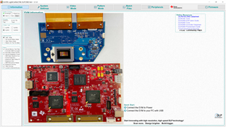
The lightCrafter show the status with the Sequencer Running box having the check mark.

But, it doesn’t seem the PLM works.

Checking the EVM, I found VOFFSET, VRESET, and VBIAS stay almot 0 voltage.

EN_OFFSET signal which is from PLM also stays low as well.

As first step, I would like to make clear why they keeps 0 voltage.

Do you have any good advice or suggestion to find the root cause?

Best Regards,

Hide

  • Hi Hide-san,

    I will assign a colleague this ticket, as they can give you a better answer.

    May we get some initial information, however?

    • Please take a picture of your set up and a close-up of your DLPLCRC900DEVM (which I will refer to your DLPC900 board/controller board from now on)
      • Please make the picture of the controller board clear so we can check jumper configuration as well
    • What LEDs come on your DLPC900 board? Which ones blink or "heartbeat," if any?
    • Are your flex cables properly connected?
    • Is J12 populated? If so, please remove the jumper and place on a single pin for safe-keeping. J12 is BOOTHOLDZ, which places the controller in bootloader mode
    • Have you programmed this controller board with any other firmware, such as the OOB firmware the DLPC900 comes with? This is to check if the board was previously working
    • Have you had any success with PLM in the past? If so, was the mirror bias kept the same in this experiment?

    Please allow us additional time to answer, as my colleague is out sick today.

    Thank you for your patience,
    Michael Ly

  • Hi Michael,

    Thank you very much for your swift reply.

    Regarding Q1 and Q2, I took three pictures and video to share the condition of my board.

    I tried to attached them to this reply but, by due to my network security restriction, I couldn't.

    So could you please tell me your e-mail address to send them directly. Sorry for inconvenient...

    For the other questions, I added my comments in Blue letter as below.

    Q3. What LEDs come on your DLPC900 board? Which ones blink or "heartbeat," if any?

    I checked them. The below is detail.

    D1 +12V GOOD LED on
    D5 FPGA DONE LED on
    D12 POWERGOOD LED on
    D6 MST RED LED off
    D7 MST GRN LED 1sec blinking
    D8 SLAVE RED LED off
    D9 SLAVE GRN LED 1sec blinking

    Q4. Are your flex cables properly connected?

    Yes they are.

    Both of them are attached correctrly as the instruction's picutre and seem to be solidly.

    Q5. Is J12 populated? If so, please remove the jumper and place on a single pin for safe-keeping. J12 is BOOTHOLDZ, which places the controller in bootloader mode.

    No, it's not.

    J12 is open. So I guess the controller isn't put in bootloader mode.


    Q6. Have you programmed this controller board with any other firmware, such as the OOB firmware the DLPC900 comes with? This is to check if the board was previously working.

    I've never updated the FW.

    As a matter of fact, this is my first time boot up trial.

    Q7. Have you had any success with PLM in the past? If so, was the mirror bias kept the same in this experiment?

    Unfortunately, I've never seen the PLM working correctly before.

    The mirror bias has an adjustment history from 1.90 to 1.32 voltage in this trial.

    Regarding the EVM's history,

    Now, I'm inquriking my co-workers who might have used the system ever before.

    If there is any new update or fact, I will share it to you as soon as possible.

    Let me know if you have any further questions.

    Best Regards,

    Hide

  • Hi Hide-san,

    Thanks for the update! I've sent you a friend request on E2E so that we can talk about this subject offline.

    Regards,
    Michael Ly

  • Hi Michael,

    Thank you for your reply.

    I sent the pictures and video file on our private message.

    First I posted the video file in MOV format but it seems not to be supported, so I've reposted it in mp4 format.

    Let me know if you have any concern or problem.

    Best Regards,

    Hide

  • Hide-san,

    Please allow Micheal and me to look at the MOV file you sent.  Also could you take an image of the GUI screen while the system is connected (make sure the status section is showing.

    Fizix

  • Hi Fizix,

    Nice to meet you.

    Attached to this reply, please find the screenshot.

    I've been using version 5.1 because 5.2 didn't show check mark box status when I tried it.

    Best Regards,

    Hide

  • Hide-san,

    Thank you for the pictures.  Let me confirm that this is actually the PLM FW.  If it is not, then this would be expected behavior and I will arrange to get the correct FW to you.

    Fizix

  • Hi Fizix, Michael,

    I have an update.

    I found that a reinforcement screw of the PLM socket was loose...

    I refasten it with a minus driver tool then the PLM started working correctly.

    The PLM's surface switched every time images on my PC changed.

    With a laser pointer lighting, things that seem like the hologram were viewed.

    Finally I've reached at the start point. My optical team can begin evaluation of the PLM.

    Thank you very much for your support and I appreciate you took time for my question.

    Best Regards,

    Hide

  • Hide-san,

    That is fantastic news.  I was about to reply that the FW version appeared to be correct.  Thanks for letting us know.

    Fizix