This thread has been locked.

If you have a related question, please click the "Ask a related question" button in the top right corner. The newly created question will be automatically linked to this question.

DLP9500: Ghost image forming in between diffraction orders

Part Number: DLP9500
Other Parts Discussed in Thread: DLP4500

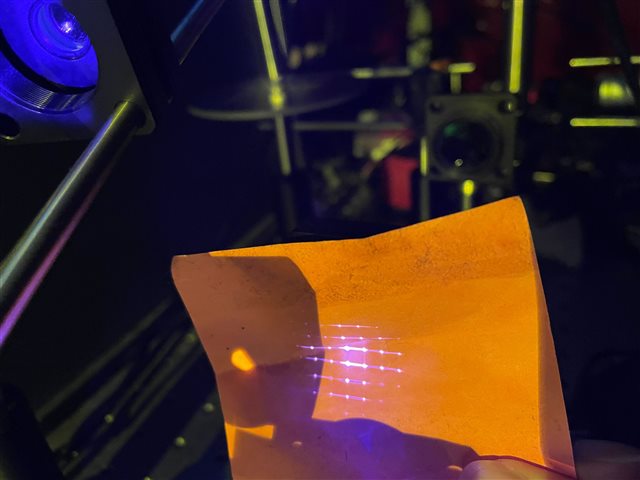
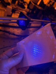
Hi, we have been having some "ghost images" forming in between diffraction orders (at the "on state" projection path) while having illumination light that is well collimated (at least we think) at 24 degrees, could you please help? We use 405nm laser light coupled with optical fiber 

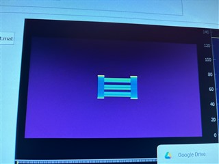
Like showing below, there are "lines" forming very closely in between the major four diffraction orders which makes it impossible to isolate just one of them. Looking closely, we can see rough "images" forming on the lines (in between the actual diffraction orders)

  • Hello X Sun,

    I have several questions that will help understand what might be happening:

    • Is there a pattern on the DMD?
    • Is there any place where the illumination beam is hitting the edge of something in the illumination path.  This could be edge diffraction
    • Could you take a picture of the pattern with all mirrors on (no pattern) and with all mirrors off (no pattern)?
    • Are you completely filling the active area of the DMD?
    • Can you take a picture of the illumination pattern on the DMD?  

    Thank you.

    Fizix

  • Hi, Fizix,

    1. yes there is a pattern on the DMD, looking like this: 

    2. this is how our illumination light look like (the square shape is very clear but there is background light). We only fill about 12mm by 12mm area on the DMD


    3. our illumination optics look like this: (starting with a multimode square shaped optical fiber and a 11mm f collimation lens, then a negative 25mm f plano concave lens, then a 150mm f plano convex lens). The background light from the dmd is hitting the edge of the 25mm f lens and thus the cage area around it. We tried to add an aperture directly before that lens to cut the background light, but it did not seem to help

    4. at completely off state, there is no light being projected. At white state, here is what the projected diffraction pattern look like, u can clearly see there are something forming right in the middle of some diffraction orders 

  • Hello again X Sun,

    Thank you for the images.  They help greatly.

    Since the DLP4500 DMD is a "diamond pixel" device what is the orientation of the DMD pattern relative to the edges of the DMD?

    It looks like the pattern has alternating "columns" on and off. creating a new periodicity.  Since you are using the DMD in the Fourier transform plane any new periodicities on the DMD greater than the pixel pitch will introduce sub-orders between the primary orders.  For example if you introduce something with a period that is 3 times the pixel pitch, then in the Fourier transform there will be suborders with a period of 1/3 of the primary orders.

    Now the vertical bars on the "H" are quite far apart so they represent a period that is many times the pixel pitch.  Therefore there will equally be as many sub-orders introduced between the primary orders in the Fourier transform image.

    If you wish to create a particular pattern in the Fourier transform it may be easier to start with it and back transform to a pattern that you need to put on to the DMD to get the desired pattern on your target.

    This is a fundamental property of using coherent light with the DMD.  If you were planning to re-image the pattern (i.e. a second Fourier transform) Then it would converge back the the "H".

    Fizix

  • Hi, thx Fizix, in the image shown above, the vertical bars of the H shape is directly parallel to the dmd edge (so no rotating for the 45d). We can look into the solution you suggested, but we don't understand even with a white field image, there are patterns forming between the diffraction orders. Any ideas? 

  • Hello X sun,

    Could you take a picture of the diffraction pattern with an all white image?  This might help me understand what is happening.

    Fizix

  • Hi, Fizix, yes, the image is actually attached above at point 4

  • X Sun,

    My error, you are correct and I missed that point. 

    The single sub-orders you see in the all on pattern is because there are some structures below the mirror with a little bit of reflectivity that have a period of 2 times the pixel pitch.  This is not something that can be gotten rid of unless you re-image the DMD itself.

    What is final goal?  It sounds like you are trying to couple the output into a fiber, or is it an image preserving bundle?

    Fizix

  • Hi, thx Fizix, could you elaborate on this point, what  are the "structures below the mirror with a little bit of reflectivity"? are those in the design of the DMD ? What do you mean by "re-image" the DMD?


    We are pretty much just use this system as a projection system for 3D printing application. We just need a clean and clear image to form in the final projection 

    Also in background of some of the images above, you can see how the illumination light is somehow being reflected back to the illumination path from the DMD. do you think that could have played an effect ?

  • X Sun,

    There are traces that are part of the design of the DMD and only show up in one direction of the diffraction pattern.

    If you use an imaging lens to re-image the surface of the DMD on your target surface all of the rays should re-converge to a correct image.

    Try putting up a lens and focus the image on to a screen.  Diffracted rays are not extraordinary, but it is more like putting up a baffle that has holes in it.  Such a baffle will not prevent the image from being re-converged, but will only reduce the power.  However diffraction does not lose power except for the orders that you do not capture.

    Fizix

  • Thank you very much Fizix, that really helps! do you have any reference manuel  or literature that discuss such problems that we can read into more

  • X Sun,

    See if the Application note that I wrote helps:  Using Lasers with DLP® DMD technology.

    Fizix

  • Thx Fizix! We were wondering if there is any documentation for srtcutures inside the DMD that is casuing additional diffraction orders that you mentioned above?

    Do such structures exist for all dmds?

  • Hello again X Sun,

    Unfortunately the actual structure is considered TI proprietary information and may be different for different DMDs.

    I cannot expound further.

    Fizix