This thread has been locked.

If you have a related question, please click the "Ask a related question" button in the top right corner. The newly created question will be automatically linked to this question.

DLPC3479: DLP4710LC nothing shows

Part Number: DLPC3479
Other Parts Discussed in Thread: DLP4710LC, , DLPA3005, DLP4710EVM-LC

Tool/software:

Hello!
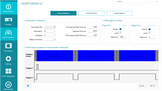
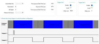
I'm using External Pattern Mode, 8-bit monochrome patterns。
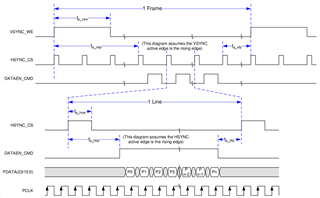
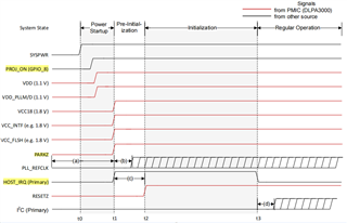
I'm uses the PARALLEL RGB interface, the timing is RGB888, and the external input is 1280*800@60hz,PDM_CVS_TE with default of active low.
But nothing shows.The hardware architecture is dlpc3479 + dlpa3005 + dlp4710lc.
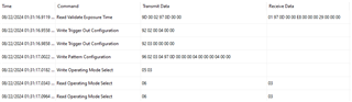
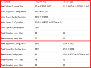
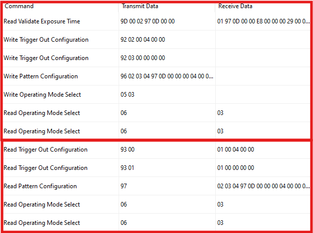
The following is the register I configured, and the corresponding value, to help me see if there is a problem。
ADDR value
8'h92 8'h02,8'h00,8'h04,8'h00,8'h00
8'h92 8'h03,8'h00,8'h00,8'h00,8'h00
8'h96 8'h02,8'h03,8'h04,8'h1A,8'h39,8'h00,8'h00,8'h00,8'h04,8'h00,8'h00,8'h00,8'h04,8'h00,8'h00
8'h05 8'h03

  • Hello!

    The PDM_CVS_TE is an optional LVCMOS I/O that can utilize 1.8V, 2.5V, 3.3V. Do you have this connected to a front-end and that's how this line is connected? The Software Programmer's Guide explains that:

    "When the parallel data mask is enabled, the DLPC3479 input PDM_CVS_TE pin functions as a data mask control for the video data on the parallel port interface. Therefore, when this functionality is enabled [1] and the mask control is active, input image frames will be ignored and the source image will not be propagated to the display. During image frames that are masked, the last unmasked image frame received will continue to be displayed. The mask control signal (PDM_CVS_TE) should only be updated during vertical blanking."

    Have you confirmed this with a scope grab?

    Are you able to utilize the GUI available on ti.com and communicate with your board? 

    If you can, could you try setting this up on the External Pattern tab as below and share the 'Command Log' found under Debug?

    Best,

    Aaron

  • Hello!
    I used my own board design, not use DLP4710EVM-LC.
    The external input is 1920*1080@60hz, in RGB888 format, but dlpc4710lc doesn't show anything.
    Here are the registers I configured.
    ADDR VALUE
    8'h92 8'h02,8'h00,8'h04,8'h00,8'h00
    8'h92 8'h03,8'h00,8'h00,8'h00,8'h00
    8'h96 8'h02,8'h03,8'h04,8'h97,8'h0D,8'h00,8'h00,8'h00,8'h04,8'h00,8'h00,8'h00,8'h04,8'h00,8'h00
    8'h05 8'h03
    Could you help me check if there is any problem.Thank you.

  • Hello,

    I've tested this on my end and using the settings you sent, the image is displayed properly. Here is the External Pattern settings as well as the Command Log:

    Best,

    Aaron

  • My external input is in RGB888 format, 1920*1080@60hz, and the clock is 148.5Mhz
    I configured the signal timing to be
    Signal            length
    VSYNC_WE  5 line
    VBP               41 line
    VFP               4 line
    HSYNC_CS  44 PCLKs
    HBP              192 PCLKs
    HFP               88 PCLKs
    And the signal timing is

    Can you check it for mistakes?
    Or provide more information about Parallel Port Input. Thank you very much!

  • Hello!

    Those settings are all within the timing requirements.

    If I'm understanding correctly, the settings you have are as below:

    Pixel Clock = 148.5MHz

    Pixels Horizontal = 1920

    Horizontal Blanking = HSYNC_CS + HBP + HFP = 44 + 192 + 88 = 324

    Total Horizontal = Pixels + Blanking = 1920 + 324 = 2244

    Horizontal Frequency = Pixel Clock/T_Horizontal = 148.5MHz/2244 = 66.176KHz

    Pixels Vertical = 1080

    Vertical Blanking = VSYNC_CS + VBP + VFP = 5 + 41 + 4 = 50

    Total Vertical = Pixels + Blanking = 1080 + 50 = 1130

    Vertical Frequency = T_Horizontal/T_Vertical = 66.176KHz/1130 = 58.56Hz

    You could check the I2C data was programmed by performing a read back on Trigger Configuration (0x93 0x00 [Trigger 0] and 0x93 0x01 [Tigger 1]), Pattern Configuration (0x97), and Operating Mode Selection (0x06). If the return isn't the same as what is sent then there's still an I2C communication issue.

    Best,

    Aaron

  • Hi TI_EXPERT

    I have two questions

    first,Parallel interface to both master and slave controller Whether to input rgb signals. If both are required, what resolution will be given to the Parallel interface?
    If I want to display a picture of 1920*1080@60hz, what is the rgb resolution given to the master and slave controllers 1920*1080@60hz? Or 960*1080@60hz?

    second,What is the timing of the iic reading the register?
    For example, when I read the 06 register, my send timing looks like this
    START 8'H36 8'H06 START 8'H37 READ STOP
    But register 05 is set to 8'H03, and register 06 reads FF.(Using an oscilloscope to view the waveform found no problems)
    May I ask why?

    Can you give me some directions for investigation?

    Thank you very much!

  • Hello,

    Parallel Interface:

    I'd recommend you to take a look at the DLP4710EVM-LC schematic. This shows that both master and slave controller need to receive all 24 parallel port input connections - this is assuming 24-bit RGB888 is desired. A full image resolution is required to give to both controllers and the information will be split to the DMD Input data lines through a configuration we provide 2 options for - see page 7 for this pin mapping selection.

    Timing of the I2C:

    If you are looking at it correctly, it seems that the mode is in standby mode (0xFF). Could you advise what the chip address of the firmware image you installed is? A Write or Read Request could be utilizing 0x36 or 0x3A. Is the system full initialized and startup flow was followed, ending with the HOST_IRQ driven low?

    I am interested in seeing your scope waveform for startup.

    Best,

    Aaron

  • Hello, Aaron Black !


    Firmware:
    The firmware I use is FWSel_DLPC3479_DLPA3005_pm2_i2c0x36_v8p4p0。

    Power-on sequence:

    host_irq signal is always low until parkz is pulled up (external pull-up resistor is connected externally).

    When resetz pulls up for a period of time, host_irq signal pulls down.
    In addition, the DLPC4710LC has a display when register 05 is configured to 01 (Display-test graphics generator mode).
    So, I don't think there's a big problem with the power-on timing.
    However, there is a problem that when the parkz signal is pulled up,
    the host_irq signal of the master controller and the slave controller are pulled up almost simultaneously,
    but the host_irq signal of the slave controller is pulled down before the host_irq signal of the master controller.

    Disconnect all the LEDs:
    We use our own board, the hardware structure is DLP4710LC + DLPC3479 + DLPA3005.
    However, the customized board is not connected to any LEDs. May I ask if I need to update the firmware?
    Can you provide a firmware image with no connected LED requirement?
    If I need to update the firmware, please send it to my email address.

    Best


    Thank you very much!

  • Hello!

    I think all of what has been mentioned is correct related to the Host_IRQ.

    I need to confirm because it's mentioned in the software programmers guide that "prior to setting the operating mode, the external source must be configured and locked. So, you need to define 96h (Write Pattern Config) and 92h (Write Trigger Out Configuration)."

    Here is the command log of both "set" and "get" for Light Control - External Pattern Streaming mode:

    Top box is 'SET', bottom box is 'GET'. Follow those set settings in that order and see if you get the same 'GET' data.

    You can change the firmware yourself through the GUI but you need to create a Batch File first. The editing can be done through Firmware - Edit Firmware - and follow the steps through there. Could you let me know what you're trying to do with disabling the LEDs through firmware?

    Best,

    Aaron

  • Hello Aaron!

    1. We make this kind of board mainly for scientific research, and we will provide external light source for dlp system.

    2. I tried to modify the firmware and set led_current to 0 (because the hardware is not connected to any led).
    However, the minimum value of led_current is 1000; otherwise, firmware cannot be generated.
    (It can be set to 0, but it cannot be saved. The saved value is still 1000)
    Please help me generate a firmware with led_current configured as 0 and send it to my email chenglongwang@juopt.com

    3. We have carried out the above operations according to your requirements.
    However, the read data is inconsistent with the written data.
    9D: 0000_0000_·····_0000_3FFF_FFFF_FFFF_FFFF
    93 00: FF_FFFF_FFFF
    93 01: FE_FEFE_FEFE
    06: FF
    According to the value of register 9D, I can't seem to use this device.
    4. Occasionally, tri_out2 cannot be configured
    The details are
    tri_out1 configuration OK(8'h92 8'h02,8'h00,8'h04,8'h00,8'h00) (all values can be written normally)
    tri_out2 configuration NG(8'h92 8'h03,8'h00,8'h00,8'h00,8'h00) (Slave does not answer when I write 8'h92)

    5. Can you provide a batch file demo?

    ##########################################
    # SET UP Write RGB LED Enable #
    ##########################################
    # Write: WRITE LED ENABLE = 7. DISABLE = 0
    W 36 52 00
    # 100 ms delay
    W 36 DB 64 00

    Could you please help check whether there is any problem with the batch file? The file file type is.bf

    6.I have tried to update the firmware, but it is still not possible。The present phenomenon is that the left half of the area is blank, and the right half of the area is slanted. But I didn't set up a splash screen, etc.Register read back still does not match。The power-on timing is normal, but when the 05 register is configured to 01 (Test Pattern Generator Mode), it does not display a screen.

    Please help to analyze the reason.
    thank you

  • Hello,

    I am reaching out to my team about these questions and will get back to you on this soon.

    Best,

    Aaron

  • I re-burned the firmware where the batchfile configuration is as follows

    ##########################################
    # SET UP Write RGB LED Enable #
    ##########################################
    # Write: WRITE LED ENABLE = 7. DISABLE = 0
    W 36 52 00
    # 100 ms delay
    W 36 DB 64 00


    But it still can't.
    And the power-on timing is out of whack. The host_irq signal is always high and does not decrease. Initialization never finished. Please help to analyze the reason

  • Hello,

    I discussed your situation with the team and it seems because the LEDs are defined as connected the PMIC. The PMIC is throwing a 'FAULT' through the INT_Z line.

    I'll reach out to you directly for a modified project that has LEDs disconnected. This should correct your issues and I2C communication should be brought back.

    Best,

    Aaron

  • Hello Aaron!

    After I burned the firmware you shared with me to flash,
    Unfortunately, the dlp4710lc does not display images, and there still seems to be a problem with iic communication. (The value of reading the 9d register is 0000_0000_·····_0000_3FFF_FFFF_FFFF_FFFF, but when the 05 register is configured as 01, the dlp4710lc can display images normally).

    Can you be of more help?

    Thank you very much!

  • Hello,

    Your statement is contradictory that there is an issue with I2C communication if you're able to configure 05 register (Operating Mode) to 01 (Test Pattern Generator). Previously you had mentioned,

    The power-on timing is normal, but when the 05 register is configured to 01 (Test Pattern Generator Mode), it does not display a screen.

    Please send me the transmitted data you sent to register 9D when it is returning what you've said (0x0000_0000_0000_0000_3FFF_FFFF_FFFF_FFFF)

    Again, you should be following this table to perform 2 tasks: 1 (top box). set Operating Mode to 03 (Light Control - External Pattern Streaming Mode) and 2 (bottom box). read back Operating Mode. This purpose was to make sure the registers were communicating correctly.

    Just as your other question - I'm getting my team to add to this - if we don't have a solution by the end of the week they can add to this.

    I need much more information than what I'm getting here to properly assess what's happening. Do you have diagrams of your communication? Or logs of what is sent and what is received? Please share any of these.

    Best,

    Aaron

  • Hello!

    1. iic communication

    The iic communication problem has been resolved.(I did not try to read back the register, potentially risky)

    2. Now there is a new problem:

    I use a self-made board, the hardware structure is dlp4710lc + dlpc3479 + dlpa3005.
    When the Display - External Video Mode is used (the 05 register is set to 00), pictures can be displayed normally.
    However, when the Light Control-External Pattern Streaming Mode is used, the dlpc4710lc only showed half the image.
    The right half can be displayed normally, and the left half is blank. It has been confirmed that the problem is from the slave controller. But I don't know what the problem is, please help to analyze it.

    3. Firmware

    The firmware version I am using is dpp3479-dual-ASIC_8.4.0.img. This firmware is custom firmware, you can not connect any LED. (In the design of self-made board, no LED is connected).(When the Display - Test Pattern Generator Mode is used, images can be displayed normally)

    4. external input

    The external input is 1920*1080@60hz, in RGB888 format.
    Here are the registers I configured.
    ADDR     VALUE
    8'h92      8'h02,8'h00,8'h04,8'h00,8'h00
    8'h92      8'h03,8'h00,8'h00,8'h00,8'h00
    8'h96      8'h02,8'h03,8'h04,8'h97,8'h0D,8'h00,8'h00,8'h00,8'h04,8'h00,8'h00,8'h00,8'h04,8'h00,8'h00
    8'h05      8'h03

    5. setting for GPIO_04 (E14) of your controllers

    As shown in the figure, GPIO_04 of the primary controller is pulled up and GPIO_04 of the secondary controller is pulled down.

    I appreciate your patience!

    Please help to analyze the reason, thank you very much