Hi,
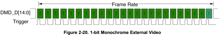
I'm trying to use the LightCrafter in HDMI input mode, with 60 Hz and 1-bit monochrome images selected to get 60 * 24 frames per second. How do I configure the external trigger output to work? Currently, pins 3 and 4 on the trigger connector (furthest away from the side edge of the board) are connected via coaxial BNC cable to a Tektronix oscilloscope. I don't have the scope specs with me, but I am guessing that it has high input impedance.
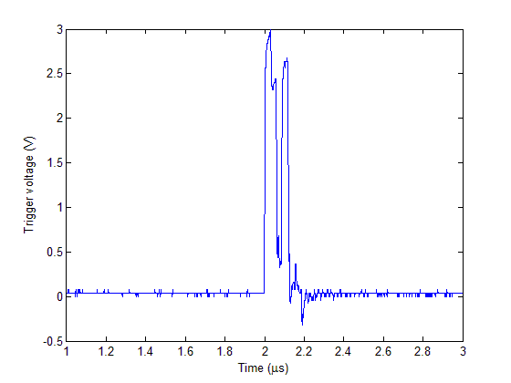
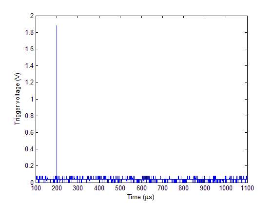
Based on the manual, I expected to see a trigger signal every frame i.e. ~0.7 ms. However, all I'm seeing is an odd spike at 60 Hz.
I've also tried the work-around suggested here: http://e2e.ti.com/support/dlp__mems_micro-electro-mechanical_systems/f/94/t/249542.aspx to enable the external trigger using the pattern sequence tab. This somehow gives me a 30 Hz trigger, but raises even more questions. For example, what is this signal synced to? Also there seems to be no way in this case to change the trigger frequency.
I'm completely baffled here. Could someone let me know if I've used the right connector here, and if so, if it is possible to get the 60 * 24 Hz signal I need?
Thanks!
p/s: Timing diagram from the manual http://www.ti.com/lit/ug/dlpu004b/dlpu004b.pdf