This thread has been locked.

If you have a related question, please click the "Ask a related question" button in the top right corner. The newly created question will be automatically linked to this question.

DLP4500: High level of FLAT state present in ON state

Part Number: DLP4500

Hi,

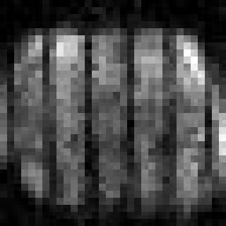
I have an optical issue with the DLP4500 that I can't seem to solve on my own. The problem is that in my microscope I have a significant amount of flat state that appears on top of my image. I have some custom DAQ software that I wrote, it uses the DLP4500EVM GUI in video mode and the DLP4500 as a second screen. I've posted some details below that could help. Figure 2. shows the typical underfilled images I've been obtaining. Comparing this to Figure 3. it's clear that the FLAT and ON states are mixing somehow, the lines of the FLAT state show up in my image collected at the ON state. My ON:OFF ratio is ~1000:1.

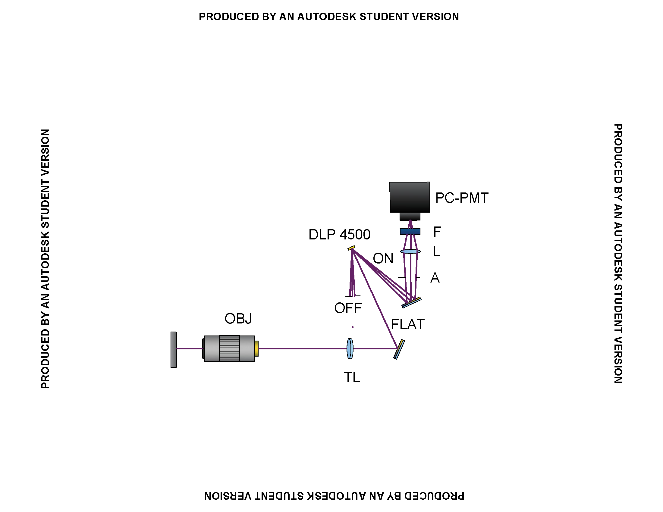
Figure 1. Simple microscope schematic. Sample is illuminated from below by a 5 mW 405 nm laser diode and the image is projected onto the DLP4500 at normal incidence. The OFF state is blocked and the ON state is sent through an aperture (<6 degree cone) and collected in a photon counting photomultiplier tube. Image is to scale.

Figure 2. Image of ON state. Object is a flat structureless piece of titanium

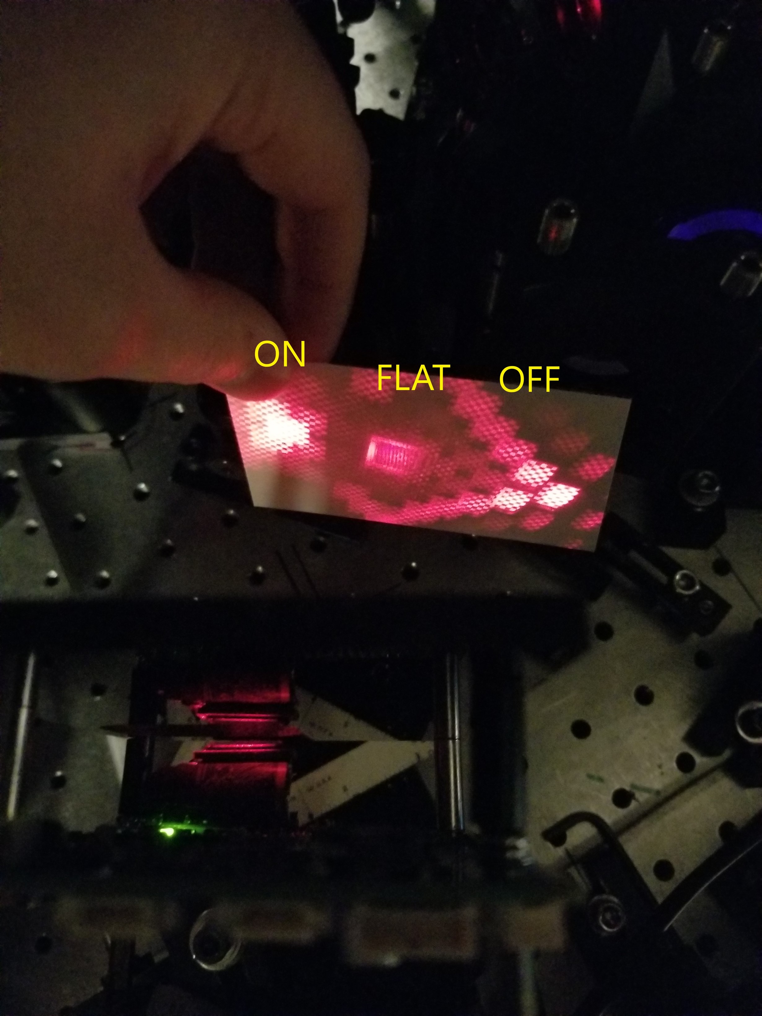
Figure 3. Appearance of ON, FLAT, and OFF states at 24 degree incident angle using 5mW HeNe laser. Default checkerboard pattern displayed. 

  • Hello Dillon,

    Could you please mark in the figure which is ON state and OFF state?

    It is very difficult guess why flat sate light in ON pupil? The DLP4500 DMD is designed to be illuminated at 24 degree angle. Is there are reason you are illuminating at normal (90 degree).  Can you change the set up such illumination is  at 24 degree.  It will create a bigger separation between On state cone and flat sate that might help improve the image. 

    The two other factors could play 

      a. Light reflected from structure under the mirror. When DMD is illuminated at normal bigger area under the mirror is exposed.

     b. ON state pupil may be getting the diffraction from OFF state.

    Please rearrange your set to illuminate the DMD at 24 degree angle and then adjust illumination angle till you get good image.

    Hopefully this helps. 

    Please let us know your findings.

    regards,

    Vivek

  • Vivek,

    I need to modulate the the image at the DMD plane. A tilt of the DMD may result in an unfocused image therefore we use a 90 degree angle. We have considered tilting the image plane with a grating, however we are trying to keep the design simple and detection efficiency high. I'll try incidence at 24 degrees and then a compromise between incident angle and image quality and let you know the results. 

    Thanks,

    Dillon Kopecky

  • Dillon,

    Thanks for the clarification. Please share your findings once ready.

    Regards,

    Mayank

  • I can confirm that at 24 degrees incident angle the same pattern is observed (Figure 4.).  I imaged the reflection from the DMD "ON" using a CCD camera and I don't see the same structure (Figure 5.). Maybe the issue is with my DAQ.

    Figure 4. Image of DMD using PMT

    Figure 5. Reflected image from DMD using CCD camera.

  • Hello Dillon,

    Thank you for sharing the update. Image 5 seems to have similar pattern as on DMD. 

    Hope the issue with DAQ software is resolved.

    regards,

    Vivek

  • Vivek,

    Thank you for being so helpful. As it turns out the grids in my PMT are casting a shadow on the image being projected from the DMD, so when I rotate the PMT the pattern also rotates. Interesting coincidence that it looks like the FLAT state. 

    Thank you,

    Dillon Kopecky