This thread has been locked.

If you have a related question, please click the "Ask a related question" button in the top right corner. The newly created question will be automatically linked to this question.

DLPDLCR2000EVM: No image seen with laser instead of LED

Part Number: DLPDLCR2000EVM
Other Parts Discussed in Thread: DLPC2607, DLP2000

Hello Forum, 

Like one previous post on making diffraction gratings, I also want to make and display my own patterns on the DMD. I understand that DLPDLCR2000EVM only allows you to display a 24-bit bmp image as a whole and no direct control over the individual mirror states. Still, I thought that if I could load a black or white image, then those two colors should correspond to ON/OFF of the mirrors (i.e. +12 or -12 degrees). Before I disassembled the light engine part (LEDs and lenses) to expose the DMD, I made sure everything that came with the package worked. For instance, I could use the Beaglebone Black and the structured light code + "pattern_disp" executable to display my own colorful images, as well as test out the python scripts.

However, once I get rid of the LEDs, display a black/white image with pattern_disp, and finally shined a 633-nm HeNe laser directly on the DMD, the result does not seem to depend on the display image. I am imaging the plane of the DMD, but I don't see any difference when I try various black/white images displayed on the DMD. Even when I now run Splash.py, I see no difference in the image.

Question: Is my understanding incorrect that totally black and totally white pixels in the 24-bit bmp image should correspond to mirrors turned to one state vs the other state (no temporal averaging)? Or are the mirrors always fixed in one state and it's the internal timing of the LEDs that make the image?

  • Hello Albert,

    Welcome to DLP forum and thank you for your interest in DLP technology.

    The DLP2000 EVM is targeted  for a display application. The DLPC2607 controller in the EVM is expecting a video image as input and converting  to a series of Red , Green and Blue planes   to create a video image. The white pixel is converted into a combination RED , GREEN and BLUE lights. It is never just one color.

    Based on you experiment, it seems your application is a light control application not a video display. I will recommend you to evaluate  EVMs target for light control.

    You can find EVM designed for light control application at the following link:

    http://www.ti.com/dlp-chip/advanced-light-control/high-speed-visible/design-development.html

    regards,

    Vivek

  • Hi Vivek,

    Thank you for your prompt response! My question is about how a given pixel value gets implemented with regard to the angle of the mirror. I understand there are LC controller versions of these chips, but right now I would like to learn more about DLP2000.

    Question 1. Let's say I have a 24-bit bmp image that is all "black", that is, the pixel has the value 0 for all three RGB. Does this mean that all 3 LEDs are supposed to be turned off OR is the mirror "off", that is, angled away from the aperture?

    Question 2. If I now display a 24-bit bmp image that is all "white", that is, the pixel has the value 255 for all three RGB, then does this mean that all 3 LEDs are on with max current with the mirror pointing toward the aperture?

    Question 3. Right now, with the LEDs off, the DMD shows no change when I put on different images. Can it be that the chip detects whether the LEDs are missing and so stops changing the DMD? The reason I ask this question is I am not sure whether the DMD mirrors ever move individually depending on the displayed image.

    If you or anyone could help me answer these _3_ questions, I'd be grateful!

  • Hi Albert,

    DMD creates an image using PWM modulation. The mirror do not stay in same state. With-in a frame the mirror will switch multiple times. The LED source are also modulated. For example to generate a 255 white pixel, LED will cycle through multiple round of RBG cycle. The DMD mirror will switch several times within each LED color cycle. Your assumption about mirrors staying in one position is not correct.

    Question 3- Very likely there is loose connection or disconnect which is prevent DMD from responding.

    regards,

    Vivek

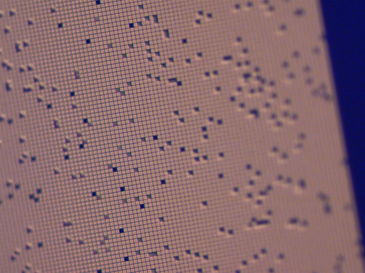
  • Thanks for your response. However, I did not think that for pure 255-255-255 images or 0-0-0 images, there would be any PWM. Also, I attached a microscope image of the DMD chip here. I checked for loose connection, but everything seemed solid. There was still no change when I displayed different images with Python and C. Based on the random array of tilted mirrors, I guess the DMD just might be broken, although the chip still recognizes that the DMD is there. Perhaps the LEDs need to be connected for this to work. 

  • Hi Albert,

    What is power of laser you are using? Some time even a small power but point beam could create enough thermal hot spot to do permanently damage to DMD.

    Based on picture, several mirrors on DMD are damaged. It is likely that DMD is non functional.

    regards,

    Vivek