This thread has been locked.

If you have a related question, please click the "Ask a related question" button in the top right corner. The newly created question will be automatically linked to this question.

TPS65987D: TPS65987D: Alternate for TPS65987D

Part Number: TPS65987D
Other Parts Discussed in Thread: TPS65988, TUSB1146

Hi,

https://e2e.ti.com/support/interface-group/interface/f/interface-forum/994379/tps65987d-alternate-for-tps65987d

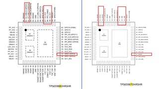
I got a suggestion to use TPS65988 as alternate part for the currently unavailable TPS65987D part. I could see the 2nd port pins in TPS65988 are GND pins in TPS65987D.

May I know how to take care of these pins in design?

Regards,

Amith K Bhat

  • Hi,

    Which pins specifically are you referring to? I would recommend following the TPS65988 datasheet and using the EVM schematic as reference, which you can see in the EVM User's Guide.

    Thank you,

    Hari

  • Hi Hari,

    Below are the pin differences. We have done the connection as per former device datasheet and just replaced the BoM with TPS65988DHRSHR.

    Following are the connections.

    1. Pin 31, 54 and 55 connected to GND through 100K resistor.

    2. Pin 45, 46, 47 are directly connected to GND.

    What is the recommendation in design to make it compatible with both parts?

    Regards,

    Amith K Bhat

  • Hi,

    Could you please update on this? We will be releasing the design for fab soon.

    Regards,

    Amith K Bhat

  • Hi,

    If you would like to use the TPS65988 for both ports then I would recommend leaving the CC pins(44 and 47) floating or with a placeholder for a resistor to GND and going to the CC pins on other port of the system. 

    For the PP2_CABLE, you may directly GND this pin and you will not have VCONN support for the port 2.

    The other pins are only GPIO pins it looks like, 31, 54 and 55 and therefore you may just leave these pins floating.

    Thank you,

    Hari

  • Hi Hari,

    Thank you for your response. Just to confirm CC pins are pin 45 and 47. I believe above one is typo.

    We are using I2C1 (pin 27 and 28) of the PD controller as a master I2C to control TUSB1146. Could you please confirm if this is ok? It was confusing in datasheet which I2C acts as a master.

    I may need your help to review the PD controller schematic to make sure we are good. Can I share the schematic over e2e chat? I have sent the connection request.

    Regards,

    Amith Bhat

  • Hi Amith,

    Yes that's correct, CC pins 45 and 47, was a typo. 

    For the I2C1, yes this port can be configured as a Master when you configure it in the GUI, but the default is slave. You can also take a look at the datasheet which should have some example block diagrams for different applications. I would also recommend taking a look at the DP Alt Mode app note if you will be supporting this: https://www.ti.com/lit/pdf/slva844

    Yes you may share the schematic here or via email if you would like to provide it in chat.

    Thank you,

    Hari

  • Thanks for the confirmation Hari. I have share the schematics over chat. Kindly review and share the feedback.

    Regards,

    Amith K Bhat

  • I have provided some feedback on the chat.