This thread has been locked.

If you have a related question, please click the "Ask a related question" button in the top right corner. The newly created question will be automatically linked to this question.

DS125RT410: Schematics review and some questions...

Part Number: DS125RT410
Other Parts Discussed in Thread: USB2ANY, DS125DF410

Dear Sirs,

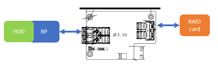
1. Attached is the customer schematics, please help to review if there is any problem with it.

2. customer wants to know how to set DS125RT410 to load EEPROM setting while power on

3. Is there any problem with jumper setting?

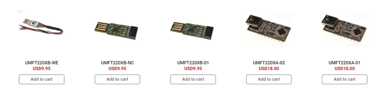
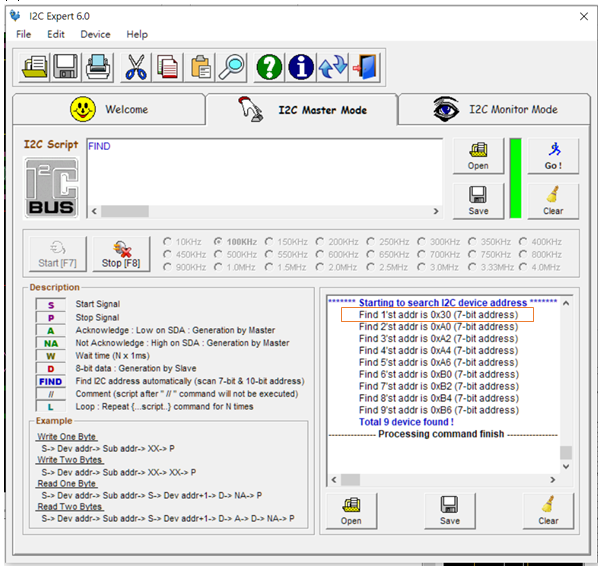
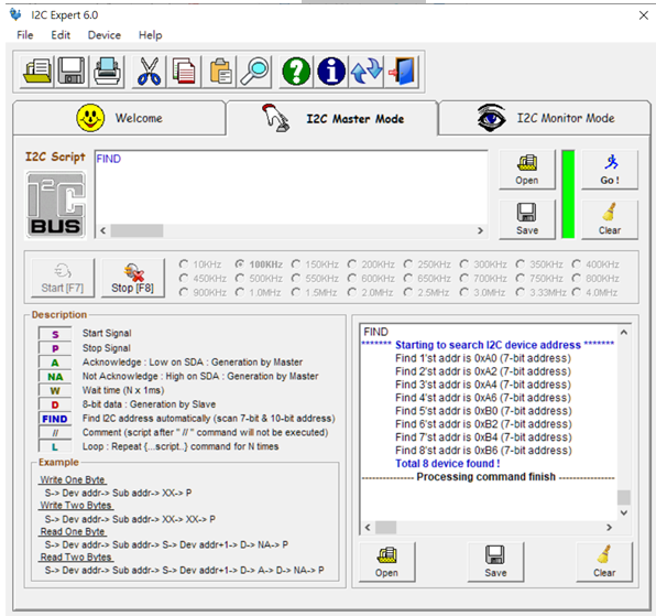
4. Is it possible for customer to use any USB to I2C dongle and their own board to work with TI GUI?

5. As customer feedback, There is signal on REFCLK_IN and REFCLK_OUT, but ALL_DONE is always HIGH.

Thanks.

3581.SCH.pdf

  • Hello Peter,

    1. Schematic review comments:
      1. U1 DS125RT410 
        1. It is recommend to place a 220 nF capacitor on the RXN and RXP pins.
        2. It is recommend that Pin 43 INT be pulled up to Vdd using a resistor with a value between 2kohms and 5kohms (currently 1kohm).
      2. U3 DS125RT410
        1. It is recommend to place a 220 nF capacitor on the RXN and RXP pins.
        2. Pin 42 REFCLK_OUT should be left floating if not used.
        3. Pin 41 ALL_DONE should be left floating.
    2. Please refer to section 7.4.1 and Section 7.5.5 of the data sheet for a description of how to set the EEPROM while powering on.
    3. Jumper comments:
      1. The loop filter jumpers should be placed across pins 1 and 2.
      2. EN_SMB jumper should be left floating for master mode and placed across pin 1 and 2 for slave mode.
    4. Yes, a USB2ANY can be used to connect from USB to I2C. The SDA and SCL pins of the USB2ANY can be connected to the SDA and SDC pins of the DS125RT410.
    5. This is most likely because EN_SMB is tied to GND.

    Regards,

    Kia Rahbar

  • Dear Sir,

    More questions need help!

    Thanks.

    1. customer had followed the suggestion and did modification but it seems still have problem with it. 

    Is there any suggestion for troubleshooting? Below is the function block and customer has connection issue now.

    2. customer use 1 EEPROM to set 2pcs DS125RT410 in EEPROM mode, did the address of both of DS125T410 need different with each other?

    3. Can customer use any brand USB to I2C dongle instead of TI USB2ANY? such as below dongles.

  • Hello Peter,

    1. Can you please provide the register settings being written to the device and the data rate they are being run at?

    2. If you are communicating to both DS125RT410 devices through the same I2C connection, both addresses must be the same.

    3. We recommend you use a TI USB2ANY. If you decide to proceed with one of the other brands, we will not be able to provide you support on communication issues.

    Regards,

    Kia Rahbar

  • Dear Sir,

    1. customer use default setting of hex file that got from E2E another post. Attached below.

    DS125DF410_example_EEPROM.zip

    2. customer already set same I2C address for both DS125RT410 but still cannot work.

    Is there any suggestion for customer?

    Thanks.

  • Hello Peter,

    I misspoke the I2C addresses for each device must be different for each DS125RT410.

    Also are you using a TI USB2ANY to communicate to the device?

    Regards,

    Kia Rahbar

  • Hi sir,

    Customer still has issues to make RT410 work.

    Here are some questions for them.

    1. customer use I2C expert to search device on I2C bus in I2C mode and found only 1 RT410(0x30) and cannot find 2nd RT410(0x32). Is there anything wrong with it?

    2. If use I2C Expert with only EEPROM, total 8 addresses will be found! Is it normal or not?

    EEPROM is CAT24C08WI-GT3

    3. while power on, customer did not enter EEPROM mode(master mode), and ALL_DONE pin is high, I2C is high, too.

    The I2C waveform as below.

    CLK:

    Data:

    Please help my customer since his RT410s still not work till now.

    Thanks.

  • Please confiirm the hardware settings implemented for the pins below for all of the retimers being evaluated.

    • EN_SMB
    • READ_EN_N
    • ADDR0, ADDR1, ADDR2, ADDR3

    It looks like you might be using 7-bit addressing with your I2C software GUI. If that's the case, the retimer slave addresses must be mapped accordingly. For example, SMBus address 0x30 corresponds to 0x18 when using 7-bit addressing. See table below.

    Table 1. DS125DF410 SMBus Write Address Assignment

    ADDR_3

    ADDR_2

    ADDR_1

    ADDR_0

    SMBus WRITE ADDRESS

    SEVEN-BIT SMBus ADDRESS

    0

    0

    0

    0

    0x30

    0x18

    0

    0

    0

    1

    0x32

    0x19

    0

    0

    1

    0

    0x34

    0x1a

    0

    0

    1

    1

    0x36

    0x1b

    0

    1

    0

    0

    0x38

    0x1c

    0

    1

    0

    1

    0x3a

    0x1d

    0

    1

    1

    0

    0x3c

    0x1e

    0

    1

    1

    1

    0x3e

    0x1f

    1

    0

    0

    0

    0x40

    0x20

    1

    0

    0

    1

    0x42

    0x21

    1

    0

    1

    0

    0x44

    0x22

    1

    0

    1

    1

    0x46

    0x23

    1

    1

    0

    0

    0x48

    0x24

    Thanks,

    Rodrigo Natal

  • Dear Sir,

    A question for RT410, did it support SAS or not?

    Thanks.

  • Hello Peter,

    DS125RT410 does not support SAS.

    Regards,

    Kia Rahbar