This thread has been locked.

If you have a related question, please click the "Ask a related question" button in the top right corner. The newly created question will be automatically linked to this question.

DS90UB941AS-Q1: Asymmetric Splitting With Cropping questions

Part Number: DS90UB941AS-Q1

Hello, 

The application diagram is as following:

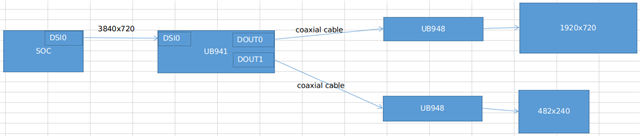
Superframe( before split)is 3840x720,and the customer referred to the datasheet “8.4.6.4.2.1 Asymmetric Splitting With Cropping" to split and crop the right side of superframe.

He configured the register according to "  RevB_941AS_SuperFrame_Calc.xlsm (snlc064.zip)". But the results are that the panel of 1920X720 could display normally, but  482x240 can't. 

Then he tried to change the superframe is 3840x320 and configured the related registers about splitting  and cropping again, the 482x240 could display normally, while 1920x720 can't due to height problem. 

He also tried to modify the below registers, but 482x240 also can't display. 

    SPLIT_CLK_SEL, SPLIT_CLK_DIV_M, SPLIT_CLK_DIV_N
    DSI_HSW_CFG_HI, DSI_HSW_CFG_LO, DSI_VSW_CFG_HI, DSI_VSW_CFG_LO
    DSI_PCLK_DIV_M, DSI_PCLK_DIV_N

His configuration is as following when he debugged:

 uVisWidth        = '3840'
    uHsyncFrontPorch = '128'
    uHsyncWidth      = '128'
    uHsyncBackPorch  = '128'
    uVisHeight       = '720'
    uVsyncFrontPorch = '3'
    uVsyncWidth      = '3'
    uVsyncBackPorch  = '3'
    uPixelFreqInHz   = '184757760'
    bDEPolarity      = '0'

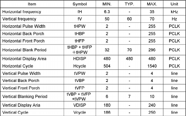
The spec of the 482x240 panel:

The configuration of DS90UB941 is: 

 0x01=0x08    #  Disable DSI */
    0x1e=0x01    #  Select FPD-Link III Port 0*/
    0x06=0x01    #  Change deser i2c addr */
    0x07=0x58
    0x08=0x5A
    0x03=0x9a    #  Enable I2C_PASSTHROUGH */
    0xc6=0x21    #  Step 1 of "8.3.8.1 Interrupt Pin (INTB)" from datasheet */
    0x40=0x04    #  Select DSI Port 0 digital registers */
    0x41=0x21    #  Select DSI_CONFIG_1 register */
    0x42=0x60    #  Set DSI_VS_POLARITY=DSI_HS_POLARITY=1 */

    0x1E=0x01    #  Select Port0  # set split mode, left/right 3D image, non-continuous clock mode
    0x5B=0x87    #  Force Splitter Mode
    0x56=0x80    #  Enable conversion of L/R image into alternating pixel image
    0x4F=0x84    #  Set 2 lane DSI
    0x1E=0x02    #  Select Port1
    0x5B=0x87    #  Force Splitter Mode
    0x56=0x80    #  Enable conversion of L/R image into alternating pixel image
    0x4F=0x84    #  Set 2 lane DSI

    0x06=0x01    #  Change deser i2c addr */
    0x07=0x58
    0x08=0x5E
    0x03=0x9a    #  Enable I2C_PASSTHROUGH */
    0xc6=0x21    #  Step 1 of "8.3.8.1 Interrupt Pin (INTB)" from datasheet */
    0x40=0x08    #  Select DSI Port 1 digital registers */
    0x41=0x21    #  Select DSI_CONFIG_1 register */
    0x42=0x60    #  Set DSI_VS_POLARITY=DSI_HS_POLARITY=1 */

    0x1E=0x01    #  Select Port0

    0x32=0x80    #  Set IMG_LINE_SIZE
    0x33=0x07    #  Set IMG_LINE_SIZE
    0x36=0x00    #  Set crop start X position (LSB)
    0x37=0x80    #  Set crop start X position (MSB)
    0x38=0x7F    #  Set crop stop X position (LSB)
    0x39=0x07    #  Set crop stop X position (MSB)
    0x3A=0x00    #  Set crop start Y position (LSB)
    0x3B=0x00    #  Set crop start Y position (MSB)
    0x3C=0xCF    #  Set crop stop Y position (MSB)
    0x3D=0x02    #  Set crop start Y position (LSB)

    0x1E=0x02    #  Select Port1

    0x36=0x00    #  Set crop start X position (LSB)
    0x37=0x80    #  Set crop start X position (MSB)
    0x38=0xE1    #  Set crop stop X position (LSB)
    0x39=0x01    #  Set crop stop X position (MSB)
    0x3A=0x00    #  Set crop start Y position (LSB)
    0x3B=0x00    #  Set crop start Y position (MSB)
    0x3C=0xEF    #  Set crop stop Y position (MSB)
    0x3D=0x00    #  Set crop start Y position (LSB)

    0x1E=0x01    #  Select Port0
    0x40=0x04    #  Select DSI digital page
    0x41=0x05    #  To reg 0x05 (TSKIP CNT)
    0x42=0x36    #  Set value for DSI+CLK
    0x40=0x08    #  Select DSI digital page
    0x41=0x05    #  To reg 0x05 (TSKIP CNT)
    0x42=0x36    #  Set value for DSI+CLK

    0x01=0x00    #  Enable DSI */

So the question is how to display the two panel normally? Does DS90UB941 support to modify the display timing/blanking? 

Best regards

Kailyn

  • Hello Kailyn,

    Based on the panel spec provided, there is no way you are going to be able to meet the timing of both of these panels with asymmetric split/crop. That's because when the cropping feature is used, the unused (cropped out) pixels/lines are converted to blanking. In this case, suppose you crop the 720 lines of the full image down to 240, then the unused 720-240 = 480 lines will be added to the vertical blanking of the smaller image (in addition to whatever blanking was already in the original superframe image). Based on the panel spec, the panel has a max vertical blanking of just 10 lines, so this will exceed the maximum spec of the panel quite significantly. There are methods to adjust the horizontal blanking after cropping and remove pixels from the blanking based on REFCLK tuning, but vertical blanking can't be removed. In order to drive these two specific screen you would need to use independent 2:2 mode and provide two individual DSI inputs to the 941AS with each one carrying one of the videos for each panel. 

    Best Regards,

    Casey 

  • Hi Casey,

    Thank you very much for your reply.

    Since the vertical blanking can't be removed, the current application should not be feasible, but what if splitter mode changes to "Asymmetric Splitting With DSI VC-IDs", is it possible to drive the two screens with one DSI input?
    (I see the following description from section of "Asymmetric Splitting With DSI VC-IDs":
        Vertical blanking for resultant video streams with virtual channels is the same as with superframe implementation, hence the smaller video stream will have larger vertical blanking.
    But I managed to drive the smaller screen with 11.64.MHz PCLK (https://e2e.ti.com/support/interface-group/interface/f/interface-forum/847206/ds90ub941as-q1-ds90ub941as-q1-asymmetric-splitting)

    Best regards

    Kailyn 

  • Hello Kailyn,

    As the datasheet mentions, the vertical blanking implications for VCID-based splitting are the same as for superframe splitting so you would have the same issue there. Also please note that 941AS has a minimum PCLK rate of 25MHz, so you may have gotten 11.64MHz to work as stated above, but this is not expected to operate over device PVT conditions so we would not advise using that configuration. 

    The superframe splitting on this part is generally most useful for driving asymmetric screens which have similar vertical dimensions or for driving panels which have a wide range of tolerance in the vertical blanking/PCLK. 

    For example an easy split to implement would be 1920x720 plus 1280x720 since they have the same vertical dimension. 

    Best Regards,

    Casey