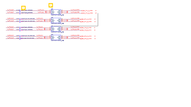
Hi
could you help to check the TUSB1044 schematic as below and any need to adjust ?
Thanks you
This thread has been locked.
If you have a related question, please click the "Ask a related question" button in the top right corner. The newly created question will be automatically linked to this question.
Hi
could you help to check the TUSB1044 schematic as below and any need to adjust ?
Thanks you
Hi David
Thank you for your detailed explanation, there are still some questions
1. It is recommended to use 0201 instead of 0402. Do I have to use 0201 cap?
2. The picture below shows that for EMI use, it will be placed close to the connector end. Are there any other suggestions?

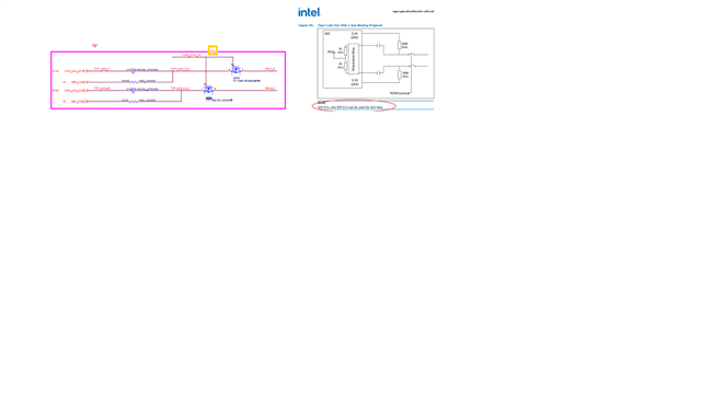
3. The circuit in the figure below refers to Intel PDG,

Hi,
1. The 201 size cap minimizes the impedance discontinuity and improve the signal integrity. For 10G, I will recommend using the 201 size cap.
2. I don't see the choke for EMI, I only see the ESD protection device, am I missing something here?
3. The issue is that you are using the TUSB1044 SBU/AUX switch to support the USB Type-C. But you also have the SBU connected directly to AUX through the FET switch. Please check with Intel on how to support SBU/AUX design over the USB Type-C.
Thanks
David
Hi David
Thanks for the kindly reply
Regarding item1, if our MB support 5G, can we use 0402 cap be available?
Item2, I wrote the wrong word, the schematic for ESD protection.
Please help review the schematic again.