This thread has been locked.
If you have a related question, please click the "Ask a related question" button in the top right corner. The newly created question will be automatically linked to this question.
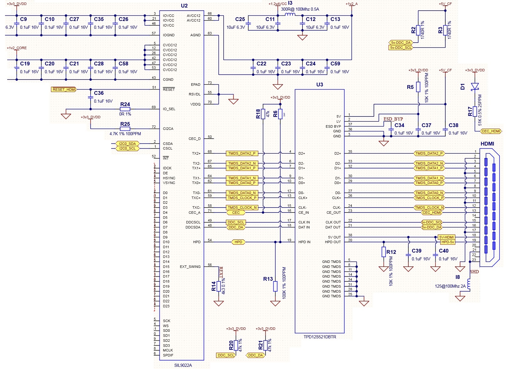
Hi, I am using a SIL9022A with a TI TPD12S521.
Note the SIL9022A states it does not require a pull on CEC with IO voltages of 3.3v. I have the IO at 3.3v on the SIL9022A driven from an AM437x.
HDMI CTS 1.4b
VCEC2 is required to be in the range 0.196v to 0.274v with VCEC1 in the range 2.88 to 3.63v.
Using the TPD12S521 as defined in the DS 27k pull, series diode to 3.3v, on CEC at the HDMI connector. With a 47k pull on CEC at the
SIL9022A (controller side).
Diode MMSD103T1G.
VCEC2 is greater than 0.274v on two test samples, under the test criteria defined by CTS 1.4b. Slightly over. 0.277v & 0.279v. Must meet this spec including tol on 27k pull to 3.3.
CEC pulled with a 27k 5% resistor to 3.3v source, & 1k pull down on CEC.
What is TI take on this issue?
I know the AM437x evm uses a different clamp (parallel) with this encoder, was there a particular reason why?
Thanks
Barrie
Hi Barrie,
For CEC, to block reverse current to the 3.3-V logic power rail, connect CEC_OUT to the 3.3-V logic level with a 27-kΩ pull-up resistor in series with a Schottky diode. 521 is only for protection, I think there is not any issue.
Regards,
Ansel
That's what I have.
Is this device HDMI CTS 1.4B compliant?
Test ID 7-15:CEC Line Degradation is what I am having issues with.
Thanks
Barrie
Hi Barrie,
Can you share the schematic and fail details? Or you can refer to https://www.ti.com/lit/an/slva747/slva747.pdf?ts=1623943090641&ref_url=https%253A%252F%252Fwww.google.com%252F#:~:text=2.7-,Test%20ID%207%2D15%3A%20CEC%20Line%20Degradation,devices%20it%20is%20attached%20to.
Ansel
Ansel, I've included part of the schematic showing the clamp and encoder.
I think I have an interaction between the SIL0922A and the clamp going on.
Thanks for the support.
Barrie
Hi Barrie,
Yes, I think you can also work with SIL0922A . And can you share the fails details?
Ansel
Ansel, I will raise a support ticket with Lattice as well.
Failure is VCEC2 is required to be in the range 0.196v to 0.274v with VCEC1 in the range 2.88 to 3.63v.
Removing TPD12S521 from the circuit, makes the design meet spec.
I am considering removing the CEC connections from the TPD12S521; can I just float the pins?
And using a TPD1E04U04DPYT for protection on the CEC line (assuming it doesn't create a problem), what do you think to that?
(I cannot find stock of TPD1E05U06, CEC is 3.3v).
Thanks
Barrie
Hi Barrie,
Yes, but it will lose ESD protection. I am just curious that I heard CEC failure first time for this device, I am not sure the test process is correct.
Regards,
Ansel