This thread has been locked.

If you have a related question, please click the "Ask a related question" button in the top right corner. The newly created question will be automatically linked to this question.

TPS25750: How to use TPS25750 GPIO to control other devicei in the system

Part Number: TPS25750
Other Parts Discussed in Thread: BQ25792, TIDA-050047, TIDA-050045

Hi teams

I have few questions about TPS25750:

  • TPS25750 have several GPIO pins, is it possible to leverage these GPIO for some basic logic control? For example, GPIO pin output high level if some condition have been met.
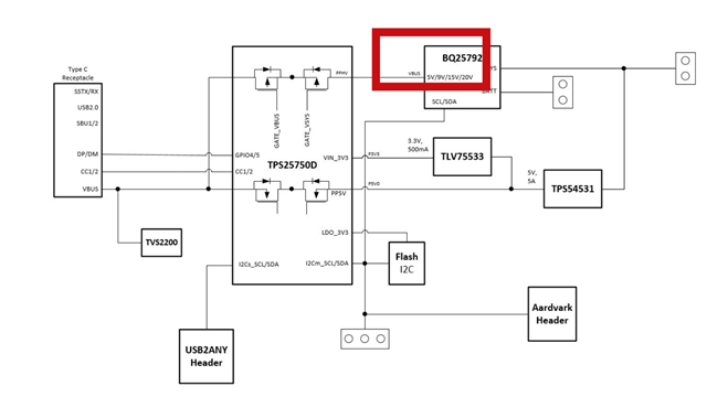
  • With TI battery charger (take BQ25792 as example) for DRP application, TPS25750 will automatically adjust BQ25792 OTG output voltage? (the high voltage source power is powered by BQ25792 through discharge the battery with OTG mode.)
  • For DRP application with BQ battery charge, is it possible to provide 3.3V for TPS25750 with BQ25792 to reduce one 5V regulator? As TPS25750 could adjust OTG output voltage, 5V also could provided by BQ25792

Thanks in advance.

  • Gabriel,

    1.  The TPS25750 GPIO pins are utilized and controlled using what we call GPIO Events.  They are described in the Technical Reference Manual detailed in this link:  TPS25750 Host Interface Technical Reference Manual.  There are several events that are commonly used to support USB3.0 muxes or to control other devices in the system.

    2.  In the case of the BQ25792, the TPS25750 will control everything necessary to configure the OTG voltage and current as well as the charge input current and VINDPM automatically using the I2C interface.  You do not need to develop any additional code for basic charging and power sourcing when using the TPS25750 with the BQ25792

    3.  The TPS25750 needs to be supplied with a 5V Buck regulator capable of supporting 3A, or whatever output current you have configured for 5V.  This is because the par uses it's internal 5V power path for all 5V sourcing operations, so the 5V busk and 3.3V LDO to supply VIN_3V3 cannot be removed from the system.

    Regards,

    Chuck

  • Chuck

    Thanks for your reply. I am looking at TIDA-050047 for reference and have few more questions:

    • In the system block diagram in TIDA-050045, will BQ25792 output 5V in OTG mode? I notice in this diagram show VBUS have 4 different output level included 5V/9V/12V/20V.
    • If we configure TPS25750 as a source device. When a device only require 5V power supply plug in, TPS25750 will power it from which power path? From PPHV pin or PP5V pin? 
    • BQ25792 should as output 5V in OTG mode, why we need extra PP5V power path?

  • Another questions about I2C

    TPS25750D have two I2C port for the host and BQcharger.

    However, in my system the MCU need to communicate with both TPS25750 and BQ25792.

    Could we share the same I2C port for these two device? If we do so, it means we tie I2C-S and I2C-M together in TPS25750, any potential risk?

    Another questions is, even we seperate two I2C port in MCU for TPS25750 and BQ25792, how to make sure MCU won't conflict with TPS25750? As PD controller will also communicate with BQ25792 for OTG control

  • Hi Gabriel,

    I believe the 5V will output from PP5V when sourcing. The main reason for this is that for sourcing, I think to meet USB-PD specification 5V must be readily present if I'm not mistaken. I will let Chuck verify this for your application.

    For the I2C portion, I think you could use the PD controller as a pass-through mode to communicate with the BQ25792 but I will let Chuck verify.

    Thank you,

    Hari

  • Hi Hari

    Thanks for your reply. For sink only application, could we just use a low current LDO to replace 5V DC-DC buck converter to reduce cost?

    Any specific current requirement for this LDO? 300mA is enough or not? (Just for TPS25750 power supply)

    Could you share more details about how to entre pass-through mode and how to connnect each I2C bus under such configuration?

  • Garbriel,

    For a sink only application, you do not need to supply the PP5V or VIN_3V3.  The part will generate it's one voltages with LDO_3V3 and LDO_1V5.

    I will provide you with a diagram of how to configure the I2C busses with a charger.

    The pass through mode utalizes the I2CR and I2CW commands in the TRM.

  • Chuck

    I don't understand how TPS25750 been powered without both PP5V and VIN_3V3.

    The internal LDO (3.3V and 1.5V) have is taking PP5V or VBUS to generate regulated output.

    Could you help me to figure it out where the power come from?

  • Gabriel,

    In what we call the dead battery condition, the TPS25750 will draw power from the VBUS pin to power all internal circuitry.

    If you only intend to SINK power with the TPS25750, then this path is sufficient and the other rails are not necessary.

    Regards,

    Chuck

  • I still not understand how to power TPS25750 through VBUS?

    VBUS voltage is coming from adatper if we not powered the PP5V.

    So it mean that when the battery not plug in, the TPS25750 won't have any power, is that right?

    If TPS25750 is power off before adapter plug in, how it detect adapter plug in event? 

  • Gabriel,

    The TPS25750 has all of the capability required to connect to a USB source with no power present in the system.  This allows the TPS25750 to be the primary power input interface for the system.

    This FAQ explains the hardware side of creating a sink only type C port.

    [FAQ] TPS25750: How do I create a Sink-Only USB-C PD port to replace a legacy Barrel Jack Connector?

  • Hi Chuck

    One more questions, if I want to finish the BQCharger initial configuration without MCU, a Flash is needed to store all initial configuration data, am I right?

    Do we have sink only device but could also finish BQcharger configuration without MCU? Thanks.

  • Gabriel,

    The BQ charger initial configuration is stored in the EEPROM for the TPS25750 and the TPS25750 will automatically configure the charger once it boots..  You are able to set the Charge Current, Charge Voltage, Charge Current Termination, and Pre-charge current for the BQ25792.

    The TPS25750 will also perform a POR configuration of the charger to support charging for these 4 conditions.

    Regards,

    Chuck

  • Do you mean that TPS25750 have internal EEPROM? Do we need external flash for BQ charger initial configuration?

  • The TPS25750 does not have an internal EEPROM.

    The part is designed to be able to boot from a 24C256 I2C EEPROM.  The program file for this EEPROM is generated by the TPS25750_Application_Customization_Tool.  The Charger settings for the BQ25792 that are configurable are listed in the GUI,