This thread has been locked.

If you have a related question, please click the "Ask a related question" button in the top right corner. The newly created question will be automatically linked to this question.

DS90UR905Q-Q1: Cannot transmit picture to UR124 chip in compatibility mode

Part Number: DS90UR905Q-Q1
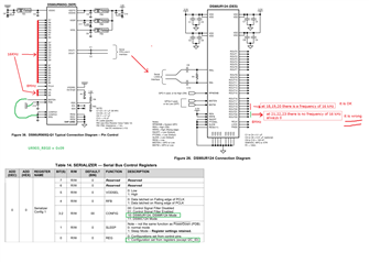
Other Parts Discussed in Thread: DS90UR241, DS90UR124

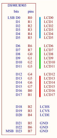
Our design includes DS90UR905 chip to transmit picture in 24 bit to the older DS90UR214 in compatibility mode.
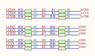
DS90UR214 design uses bits 21 22 23 for DE HS VS.
For some reason we cannot receive anything on those pins when we transmit the picture via DS90UR905. They go through fine when UR124 is used.
We get the proper signal (test signal 16KHz) on all pins except 21 22 23. CLK is correct. LCK = 1.
Anything we do wrong ? The connection diagram is attached.
Please let us know if anything we are doing wrong and what should we try ?

  • Hi Dmitry,

    The connection looks ok. Have you tried to strap the UR905 into backward mode instead of using the register option?

    Best Regards,

    Charley Cai

  • Let us try to resolder everything and use these HW pins for mode select. Any other reason why the higher bits are not populating ?

  • Hello Dmitry,

    Please let us know the result of the additional testing - outside of that we will brainstorm any reason why the higher bits are not coming through but nothing obvious comes to mind at the moment 

    Best Regards,

    Casey 

  • We now have CONFIG[1:0] = 10: interfacing to DS90UR241. All default settings otherwise.

    We do see the signal on all pins except 21 22 23. 

    The same signal is fed to all pins including DE HS VS.

    We tried playing with REG2, there is some influence on signal (sync becoming unstable), no influence on 21 22 23.

    Can you simulate that situation and let us know if everything works on your side ?

  • Hey Dmitry,

    Are you feeding the signal on the 905 side also the R[7]/B[7]/G[7] signals?

    Best Regards,

    Casey 

  • Yes please refer to the connection diagram in red color. We feed 16KHz (DE) signal to all pins including DE VS HS. 

    We do get this signal on all pins on UR241 except 21 22 23. 

  • Hello Dmitry,

    Can you share the actual schematics for both ends here? It looks like the pictures you have posted are just the typical applications diagrams from our datasheets. 

    I'm still not seeing any obvious reason why this would happen. We don't have any simulation models available for these parts at the moment - both are legacy device in our portfolio so even having hardware on hand to make this kind of connection and try on our end may be a difficult prospect at this point. But please share your schematics in the meantime and I'll take a look.

    Best Regards,

    Casey 

  • The schematics for 241 is not ours, so we do not have it. The 241 board works fine with 124 chip. The schematics for our design as attached. Exactly same as your reference. We tried few different board, few ICs and they all work the same. No higher bits at receiver.

    .vb_FPD2dev_V3R2.PDF

  • Dmitry,

    From the schematic it looks like the default stuffing resistors hard tie HS/VS/DE inputs to GND as well as B5/B6/B7:

    Is this correct?

    Best Regards,

    Casey 

  • All these resistors are removed on our DEV board and external DE signal is fed to all 0..23, DE, VS, HS pins. So all 27 pins are fed the same signal.

  • Here is the picture of the actual board

  • Hello Dmitry,

    Ok, at the moment I can't see any reason why this would be happening but next week we will check to see if we have any dev HW for these legacy parts which we could use to emulate your setup and check what we see. 

    Thank you for your patience

    Best Regards,

    Casey 

  • If you can try that scenario real quick and confirm you have it working, it will be perfect. We tried pretty much everything, nothing in errata or any application notes.

  • Hello Dmitry,

    Ok, please give us a few days to see if we can locate any boards for these legacy devices and we will get back to you 

    Best Regards,

    Casey 

  • Appreciate your support on this. If we can help with anything, let me know. We really need some resolution here.. Would hate to go back to 124 chip. We ideally wanted to support a wide range of ICs with one simple design. From your docs it seemed possible.

  • Hello Dmitry,

    I was able to locate boards for both UR905 and UR124 today in our storage space so we are working on getting them powered up, connected, and setting up a function generator for PCLK+input signals so once we have it up and running I'll let you know 

    Best Regards,

    Casey 

  • Hi Dmitry,

    I helped Casey setup the UR905+UR124 and I may have found the issue. The UR905 has a total of 27 LVCMOS Parallel Input Pins and the UR124 has a total of 24 LVCMOS Parallel Output Pins. There are a total of 21 input/output pin pairs. See the relationship between the pins in the table below:

    DS90UR905 -> DS90UR124
    R2 -> ROUT0

    R3 -> ROUT1

    R4 -> ROUT2
    R5 -> ROUT3
    R6 -> ROUT4
    R7 -> ROUT5
    G2 -> ROUT6
    G3 -> ROUT7
    G4 -> ROUT8
    G5 -> ROUT9
    G6 -> ROUT10
    G7 -> ROUT11
    B2 -> ROUT12
    B3 -> ROUT13
    B4 -> ROUT14
    B5 -> ROUT15
    B6 -> ROUT16
    B7 -> ROUT17
    HS -> ROUT18
    VS -> ROUT19
    DE -> ROUT20

    The input pins R0, R1, G0, G1, B0, and B1 on the UR905 do nothing in this configuration. Any signal applied there will not be passed to the connected UR124. And pins ROUT21-23 on the UR124 will not output anything in this configuration. You are experiencing expected behavior.

    In the provided schematic, you are connecting LCD0 to R0. You need to change this and connect LCD0 to R2. And also make subsequent changes based on the table I provided above.

    Best,

    Justin Phan

  • Thank you Justin,

    Is there a way for us to pass information into bits 21 22 23 to UR124 from UR905 in compatibility mode ? These bits are used for HS VS DE in legacy UR124 design which we interact with. We have no way to change the legacy device. 

    So UR905 is not really backward compatible with UR124 then ?

  • Hello Dmitry,

    UR905 is compatible with UR124. As Justin explained, when pairing the two devices 21 bits are passed from SER to DES which allows you to transfer 18bpp + HS/VS/DE. There is no way to reconfigure whether the MSBs or LSBs of the UR124 are used in this mode. This specific pairing always uses the LSBs ROUT[0]-ROUT[20] of the UR124 so if you want to use this specific pairing for 18bit color you would need to adjust the UR124 design. 

    Best Regards,

    Casey 

  • Ok, this is not our sense of "compatibility".

    I'm wondering why is this very important information is not covered in Application Note or Errata ? We relied on compatibility in a full sense and got only very limited features. If this information is disclosed in the Manual or Errata, we would not spend the last month pulling the hairs out.

  • Can we expect the same surprises in "compatibility" if we use UR241 with C124 (one of the legacy designs we deal with) for example ? Any known limitations on compatibility we should be aware of before we pull a trigger ?

  • Hello Dmitry,

    I'm sorry that this situation has caused struggles for you and I agree that this could be made more clear in the device documentation to avoid confusion. In fact, in newer devices such as DS90UR907 this point was made more clear in the datasheet documentation (take a look at table 7 from the UR907 datasheet), but at the time of UR905 release, that was not included explicitly. The UR905 datasheet just makes mention of the fact that color mapping should be reviewed when pairing with backwards compatible configurations for this reason so feel free to reach out to us in the future for support on topics such as this during the design phase. 

    For UR241 to C124 compatibility you will be able to use all 24 bits the same way as UR241 to UR124 or C241 to C124. The only difference is in the FPD II encoding on the link side where UR241 incorporates a LSFR randomizer to improve DC balance. If you turn this off, by setting RAOFF = H (which is required to pair with C124), then UR241 will act just like C241. 

    Best Regards,

    Casey 

  • Sounds good. We will proceed with UR241 design then. Thanks for you help.