This thread has been locked.

If you have a related question, please click the "Ask a related question" button in the top right corner. The newly created question will be automatically linked to this question.

TPS65987EVM: Using the Devkit with the 10G-EXPANSION-EVM to do display port alt mode

Part Number: TPS65987EVM
Other Parts Discussed in Thread: TPS65987, TUSB1064

I am trying to configure the TPS65987 so that the EVM will source vbus and be a DRP port. when  a device is plugged in it will by default initiate to UFP. Using the 10G-EXPANSION-EVM i would like to put the device into alt mode with usb. The devices i have tried to connect is a Samsung S9. With the S9 i have demonstrated this capability with a off the shelf solution. when i plug it into the devkit the phone begins to charge and get usb2 device to connect to the phone. The LEDs on the EVM indicate that DP and USB3 is active and the flip LED will illuminate when i flip the cable. I do not get usb 3 or display port output to a monitor. I have attached the config project which i flash to ram after boot but before phone is connected. Also attached is an images of the setup. Also attached is the debug registers from the devkit once the phone is connected.

I used this devkit and the 10G-EXPANSION-EVM to create a custom solution. On the custom solution with the same config i get the same symptoms but i am able to get usb3 device to connect to the phone. But i do not get display port signals through

I have a suspicion that the 10G-EXPANSION-EVM some how broke and is not letting any signals though but i have verified that the board is powered and current draws seem normal. I was wondering if there are any suggestions on what else i can do to debug this issue or maybe if there is an issue with the config file
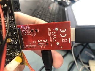
10G-EXPANSION-EVMoverall devkit setupTPS65987EVM_setup.pjt.debug_snap.zipclose up

  • I don't see HPD happening. HPD pin from the Expansion board connects to GPIO3 for HPD. If for some reason the HPD doesn't toggle then you will not see HPD attention message go to the phone and phone will not see that there is display connected.

    HPD_LED(D2_Ba)  should glow if there is HPD signal from the monitor.

    If that doesn't happen then either the Monitor is not sending HPD or the expansion board is broken.

  • The HPD at the connector is 2.75V at the connector when there is no monitor connected. when i connect the monitor then pin drops to 2.5V. Sounds like the board is broken. on the custom board the signal goes from 0v when not connected to 3.2V when connected. attached are the debug registers which DP status tx status says its high. what other debug steps do you recommend? 

    debug_snap_custom_board.zip

  • The state machine trace you provided this time was empty, could you capture that again? Or if you have PD trace from Analyzer like Totalphase that will help to check if the HPD message exchange happened.

    Is custom board a different board where you tested HPD to be toggling correctly or is that again an expansion board?

    Other things you can do assuming that message exchange is good is to reduce the size of the cables. Try to use lower resolution to see if there is not signal integrity issues. If you have Aux analyzer you can check to see if the Display negotiation is happening.

  • that's odd that it shows unknown the way it does. i took another snapshot and it looks similar. i also just did a download and copy paste of just the pd state machine right after i plug the phone it and i get a little more info, but it looks like its getting drowned out by this unknown message not sure what the issue is. 

    This custom board is a complete board with the pd controller and the usb mux with display port and type c connectors. Its setup for a flashless boot into config 2 with the boot strap then with a micro patch it over i2c (micro not shown). attached is the schematic and image of schematic. note the protection ic is missing and jumped due to art shortage (u1 on schematic). the HPD seems to toggle right and the DP status tx status says its high.

    i can look into getting shorter cables currently don't have any shorter cables. I cant select the resolution the phone and computer (computer has been tested with a type c to hdmi alt mode adaptor to prove that computer supports alt mode)doesn't detect a monitor. 

    would you recommend this pd analyzer 

    https://www.totalphase.com/products/usb-power-delivery-analyzer/

    what do you recommend for a aux analyzer.

    PD Test PCB w ALT MODE.pdf 

    Port 1	Module 31	0x1ff = UNKNOWN
    Port 0	Module 0	0x10 = UNKNOWN
    Port 0	Module 0	0x11 = UNKNOWN
    Port 0	Module 11	0x0 = UNKNOWN
    Port 0	Module 0	0x10 = UNKNOWN
    Port 0	Module 0	0x11 = UNKNOWN
    Port 0	Module 0	0x10 = UNKNOWN
    Port 0	Module 0	0x11 = UNKNOWN
    Port 0	Module 0	0x10 = UNKNOWN
    Port 0	Module 0	0x11 = UNKNOWN
    Port 0	Module 0	0x10 = UNKNOWN
    Port 0	Module 0	0x11 = UNKNOWN
    Port 0	Module 0	0x10 = UNKNOWN
    Port 0	Module 0	0x11 = UNKNOWN
    Port 0	Module 0	0x10 = UNKNOWN
    Port 0	Module 0	0x11 = UNKNOWN
    Port 0	Module 0	0x10 = UNKNOWN
    Port 0	Module 0	0x11 = UNKNOWN
    Port 0	Module 0	0x10 = UNKNOWN
    Port 0	Module 0	0x11 = UNKNOWN
    Port 0	Module 0	0x10 = UNKNOWN
    Port 0	Module 0	0x11 = UNKNOWN
    Port 0	Module 0	0xe = UNKNOWN
    Port 0	Module 0	0xa = UNKNOWN
    Port 0	INT	0x19 = DATA_STATUS_UPDATE
    Port 0	INT	0x3 = PLUG_INSERT_OR_REMOVAL
    Port 0	PD	0x2 = PEState_LaunchPolicyEngine
    Port 0	PD	0x2e = PEState_Enable_VCONN
    Port 0	PD	0x2f = PEState_Enable_VBUS
    Port 0	Module 9	0xc = UNKNOWN
    Port 0	Module 9	0x0 = UNKNOWN
    Port 0	Module 11	0x0 = UNKNOWN
    Port 0	PD	0x13 = PEState_Source_Startup
    Port 0	PD	0x96 = PESTATE_SRC2PLUG_VDM_Identity_Request
    Port 0	Module 8	0xf = UNKNOWN
    Port 0	Module 8	0x7 = UNKNOWN
    Port 0	Module 8	0x8 = UNKNOWN
    Port 0	Module 8	0xc = UNKNOWN
    Port 0	Module 8	0x11 = UNKNOWN
    Port 0	Module 8	0x5 = UNKNOWN
    Port 0	Module 8	0x1c = UNKNOWN
    Port 0	Module 8	0x7 = UNKNOWN
    Port 0	Module 8	0x8 = UNKNOWN
    Port 0	Module 8	0xc = UNKNOWN
    Port 0	Module 8	0x16 = UNKNOWN
    Port 0	PD	0x97 = PESTATE_SRC2PLUG_VDM_Identity_ACKed
    Port 0	PD	0x14 = PEState_Source_Startup_Continue
    Port 0	PD	0x16 = PEState_Source_SendCapabilities
    Port 0	Module 8	0xf = UNKNOWN
    Port 0	Module 8	0x7 = UNKNOWN
    Port 0	Module 8	0x8 = UNKNOWN
    Port 0	Module 8	0xc = UNKNOWN
    Port 0	Module 8	0x11 = UNKNOWN
    Port 0	Module 8	0x7 = UNKNOWN
    Port 0	Module 8	0x8 = UNKNOWN
    Port 0	Module 8	0xc = UNKNOWN
    Port 0	Module 8	0x16 = UNKNOWN
    Port 0	PD	0x19 = PEState_Source_NegotiateCapability
    Port 0	PD	0x1b = PEState_Source_TransitionSupply_Accept
    Port 0	Module 8	0xf = UNKNOWN
    Port 0	Module 8	0x7 = UNKNOWN
    Port 0	Module 8	0x8 = UNKNOWN
    Port 0	Module 8	0xc = UNKNOWN
    Port 0	Module 8	0x11 = UNKNOWN
    Port 0	PD	0x1c = PEState_Source_TransitionSupply
    Port 0	PD	0x1e = PEState_Source_TransitionSupply_SetAlarmsNew
    Port 0	PD	0x1f = PEState_Source_TransitionSupply_PS_RDY
    Port 0	Module 8	0xf = UNKNOWN
    Port 0	Module 8	0x7 = UNKNOWN
    Port 0	Module 8	0x8 = UNKNOWN
    Port 0	Module 8	0xc = UNKNOWN
    Port 0	Module 8	0x11 = UNKNOWN
    Port 0	PD	0x17 = PEState_Source_Ready
    Port 0	Module 8	0x17 = UNKNOWN
    Port 0	Module 8	0x0 = UNKNOWN
    Port 0	Module 8	0x1 = UNKNOWN
    Port 0	PD	0x56 = PEState_DRS_Send_DR_Swap
    Port 0	Module 8	0xf = UNKNOWN
    Port 0	Module 8	0x7 = UNKNOWN
    Port 0	Module 8	0x8 = UNKNOWN
    Port 0	Module 8	0xc = UNKNOWN
    Port 0	Module 8	0x11 = UNKNOWN
    Port 0	Module 8	0x5 = UNKNOWN
    Port 0	Module 8	0x18 = UNKNOWN
    Port 0	Module 8	0x7 = UNKNOWN
    Port 0	Module 8	0x8 = UNKNOWN
    Port 0	Module 8	0xc = UNKNOWN
    Port 0	Module 8	0x16 = UNKNOWN
    Port 0	PD	0x55 = PEState_DRS_DFP_UFP_Change_to_UFP
    Port 0	PD	0x17 = PEState_Source_Ready
    Port 0	Module 8	0x17 = UNKNOWN
    Port 0	Module 8	0x0 = UNKNOWN
    Port 0	Module 8	0x1 = UNKNOWN
    Port 0	PD	0xe = PEState_GetCap
    Port 0	Module 8	0xf = UNKNOWN
    Port 0	Module 8	0x7 = UNKNOWN
    Port 0	Module 8	0x8 = UNKNOWN
    Port 0	Module 8	0xc = UNKNOWN
    Port 0	Module 8	0x11 = UNKNOWN
    Port 0	Module 8	0x5 = UNKNOWN
    Port 0	Module 8	0x18 = UNKNOWN
    Port 0	Module 8	0x7 = UNKNOWN
    Port 0	Module 8	0x8 = UNKNOWN
    Port 0	Module 8	0xc = UNKNOWN
    Port 0	Module 8	0x16 = UNKNOWN
    Port 0	PD	0xf = PEState_GetCap_Rx
    Port 0	PD	0x17 = PEState_Source_Ready
    Port 0	Module 8	0x17 = UNKNOWN
    Port 0	Module 8	0x0 = UNKNOWN
    Port 0	Module 8	0x1 = UNKNOWN
    Port 0	PD	0xe = PEState_GetCap
    Port 0	Module 8	0xf = UNKNOWN
    Port 0	Module 8	0x7 = UNKNOWN
    Port 0	Module 8	0x8 = UNKNOWN
    Port 0	Module 8	0xc = UNKNOWN
    Port 0	Module 8	0x11 = UNKNOWN
    Port 0	Module 8	0x5 = UNKNOWN
    Port 0	Module 8	0x18 = UNKNOWN
    Port 0	Module 8	0x7 = UNKNOWN
    Port 0	Module 8	0x8 = UNKNOWN
    Port 0	Module 8	0xc = UNKNOWN
    Port 0	Module 8	0x16 = UNKNOWN
    Port 0	PD	0xf = PEState_GetCap_Rx
    Port 0	PD	0x17 = PEState_Source_Ready
    Port 0	Module 8	0x17 = UNKNOWN
    Port 0	Module 8	0x0 = UNKNOWN
    Port 0	Module 8	0x7 = UNKNOWN
    Port 0	Module 8	0x8 = UNKNOWN
    Port 0	Module 8	0xc = UNKNOWN
    Port 0	Module 8	0x16 = UNKNOWN
    Port 0	Module 8	0x6 = UNKNOWN
    Port 0	Module 8	0x19 = UNKNOWN
    Port 0	PD	0x5c = PEState_UFP_VDM_Send_Identity
    Port 0	Module 8	0xf = UNKNOWN
    Port 0	Module 8	0x7 = UNKNOWN
    Port 0	Module 8	0x8 = UNKNOWN
    Port 0	Module 8	0xc = UNKNOWN
    Port 0	Module 8	0x11 = UNKNOWN
    Port 0	PD	0x17 = PEState_Source_Ready
    Port 0	Module 8	0x17 = UNKNOWN
    Port 0	Module 8	0x0 = UNKNOWN
    Port 0	Module 8	0x7 = UNKNOWN
    Port 0	Module 8	0x8 = UNKNOWN
    Port 0	Module 8	0xc = UNKNOWN
    Port 0	Module 8	0x16 = UNKNOWN
    Port 0	Module 8	0x6 = UNKNOWN
    Port 0	Module 8	0x19 = UNKNOWN
    Port 0	PD	0x5d = PEState_UFP_VDM_Send_SVIDs
    Port 0	Module 8	0xf = UNKNOWN
    Port 0	Module 8	0x7 = UNKNOWN
    Port 0	Module 8	0x8 = UNKNOWN
    Port 0	Module 8	0xc = UNKNOWN
    Port 0	Module 8	0x11 = UNKNOWN
    Port 0	PD	0x17 = PEState_Source_Ready
    Port 0	Module 8	0x17 = UNKNOWN
    Port 0	Module 8	0x0 = UNKNOWN
    Port 0	Module 8	0x7 = UNKNOWN
    Port 0	Module 8	0x8 = UNKNOWN
    Port 0	Module 8	0xc = UNKNOWN
    Port 0	Module 8	0x16 = UNKNOWN
    Port 0	Module 8	0x6 = UNKNOWN
    Port 0	Module 8	0x19 = UNKNOWN
    Port 0	PD	0x5e = PEState_UFP_VDM_Send_Modes
    Port 0	Module 8	0xf = UNKNOWN
    Port 0	Module 8	0x7 = UNKNOWN
    Port 0	Module 8	0x8 = UNKNOWN
    Port 0	Module 8	0xc = UNKNOWN
    Port 0	Module 8	0x11 = UNKNOWN
    Port 0	PD	0x17 = PEState_Source_Ready
    Port 0	Module 8	0x17 = UNKNOWN
    Port 0	Module 8	0x0 = UNKNOWN
    Port 0	Module 8	0x7 = UNKNOWN
    Port 0	Module 8	0x8 = UNKNOWN
    Port 0	Module 8	0xc = UNKNOWN
    Port 0	Module 8	0x16 = UNKNOWN
    Port 0	Module 8	0x6 = UNKNOWN
    Port 0	Module 8	0x19 = UNKNOWN
    Port 0	PD	0x5f = PEState_UFP_VDM_Evaluate_Mode_Entry
    Port 0	PD	0x60 = PEState_UFP_VDM_Mode_Entry_ACK
    Port 0	Module 8	0xf = UNKNOWN
    Port 0	Module 8	0x7 = UNKNOWN
    Port 0	Module 8	0x8 = UNKNOWN
    Port 0	Module 8	0xc = UNKNOWN
    Port 0	Module 8	0x11 = UNKNOWN
    Port 0	PD	0x17 = PEState_Source_Ready
    Port 0	Module 8	0x17 = UNKNOWN
    Port 0	Module 8	0x0 = UNKNOWN
    Port 0	Module 8	0x7 = UNKNOWN
    Port 0	Module 8	0x8 = UNKNOWN
    Port 0	Module 8	0xc = UNKNOWN
    Port 0	Module 8	0x16 = UNKNOWN
    Port 0	Module 8	0x6 = UNKNOWN
    Port 0	Module 8	0x19 = UNKNOWN
    Port 0	PD	0x66 = PEState_UFP_VDM_Status_Request
    Port 0	Module 8	0xf = UNKNOWN
    Port 0	Module 8	0x7 = UNKNOWN
    Port 0	Module 8	0x8 = UNKNOWN
    Port 0	Module 8	0xc = UNKNOWN
    Port 0	Module 8	0x11 = UNKNOWN
    Port 0	PD	0x17 = PEState_Source_Ready
    Port 0	Module 8	0x17 = UNKNOWN
    Port 0	Module 8	0x0 = UNKNOWN
    Port 0	Module 8	0x7 = UNKNOWN
    Port 0	Module 8	0x8 = UNKNOWN
    Port 0	Module 8	0xc = UNKNOWN
    Port 0	Module 8	0x16 = UNKNOWN
    Port 0	Module 8	0x6 = UNKNOWN
    Port 0	Module 8	0x19 = UNKNOWN
    Port 0	PD	0x67 = PEState_UFP_VDM_Config_Request
    Port 0	PD	0x68 = PEState_UFP_VDM_Config_ACK
    Port 0	Module 8	0xf = UNKNOWN
    Port 0	Module 8	0x7 = UNKNOWN
    Port 0	Module 8	0x8 = UNKNOWN
    Port 0	Module 8	0xc = UNKNOWN
    Port 0	Module 8	0x11 = UNKNOWN
    Port 0	PD	0x17 = PEState_Source_Ready
    Port 0	Module 3	0x1 = UNKNOWN
    Port 0	INT	0x19 = DATA_STATUS_UPDATE
    Port 0	Module 8	0x17 = UNKNOWN
    Port 0	Module 8	0x0 = UNKNOWN
    Port 0	Module 2	0x6 = UNKNOWN
    Port 0	Module 8	0x17 = UNKNOWN
    Port 0	Module 8	0x0 = UNKNOWN
    Port 0	Module 8	0x1 = UNKNOWN
    Port 0	PD	0x65 = PEState_UFP_VDM_Attention_Request
    Port 0	Module 8	0xf = UNKNOWN
    Port 0	Module 8	0x7 = UNKNOWN
    Port 0	Module 8	0x8 = UNKNOWN
    Port 0	Module 8	0xc = UNKNOWN
    Port 0	Module 8	0x11 = UNKNOWN
    Port 0	Module 8	0x5 = UNKNOWN
    Port 0	Module 8	0x19 = UNKNOWN
    Port 0	PD	0x17 = PEState_Source_Ready
    Port 0	Module 8	0x17 = UNKNOWN
    Port 0	Module 8	0x0 = UNKNOWN
    Port 0	Module 11	0x0 = UNKNOWN
    Port 0	Module 11	0x0 = UNKNOWN
    Port 0	Module 11	0x1 = UNKNOWN
    Port 0	Module 11	0x0 = UNKNOWN
    Port 0	Module 11	0x0 = UNKNOWN
    Port 0	Module 11	0x1 = UNKNOWN
    Port 0	Module 11	0x0 = UNKNOWN
    Port 0	Module 11	0x0 = UNKNOWN
    Port 0	Module 11	0x1 = UNKNOWN
    Port 0	Module 11	0x0 = UNKNOWN
    Port 0	Module 11	0x0 = UNKNOWN
    Port 0	Module 11	0x1 = UNKNOWN
    Port 0	Module 11	0x0 = UNKNOWN
    Port 0	Module 11	0x0 = UNKNOWN
    Port 0	Module 11	0x1 = UNKNOWN
    Port 0	Module 11	0x0 = UNKNOWN
    Port 0	Module 11	0x0 = UNKNOWN
    Port 0	Module 11	0x1 = UNKNOWN
    Port 0	Module 11	0x0 = UNKNOWN
    Port 0	Module 11	0x0 = UNKNOWN
    Port 0	Module 11	0x1 = UNKNOWN
    debug_snap_custom_boardr3.zip

  • This is a better log, so I think the PD portion looks to be good. I know Ellysis tracker can do Aux, but there might be some cheaper options too. On other things you can do is capture the SBU lines on scope or a logic analyzer to start with. 

    Could you share the project file for the customer board. Since you are using GPIO controls to control TUSB1064 you can monitor those to make sure the device is working correctly. It might be good time to contact HSP after that. 

  • Ok ill try and get the Ellysis. Attached is a capture of the SBU/AUX lines. the blue and yellow signals are display port connector side and the purple green are the type c connector side. The signals look good for LVDS.

    the project file is the same as i was using on the dev kit. I have checked the GPIO controls and they look to be functioning. they are high when the phone is plugged in indicating to the USB mux that USB3 and DP is active. The flip will react correctly when the cable is flipped. USB3 functions through the mux.

    5706.TPS65987EVM_setup.pjt

    SBU signals

  • I think, it is time to reach out to the HSSC team for support on the mux. I think PD controller is doing what it supposed to.

  • Carlson,

    Did you get any further on this? Do you need help getting this to HSSC team?

  • Yes i need help getting a hold of the HSSC Tesm

  • Hi Carlson,

    I will be able to help with the mux. Is the mux being configured over GPIO or I2C? Just ot mkae sure I am tracking can you share your most recent results? (i.e USB 3 working and DP not working, etc.) 

  • Hi Malik 

    thanks for the help in advance. The mux is being configured over GPIO. Usb3 is working and Display port isnt. the aux channel appears to be working as i noted the signals are going through the mux. HPD is being detected.

  • Hi Carlson,

    What is the state of CTL0, CTL1, and FLIP during your tests? These pins should correspond to a GPIO on your PD controller. 

  • yes i have verified that the CTL0 CTL1 map to being high 3.3 when the device is plugged in to signify that a device with usb3 and dp is connected. The flip will track with cable orientation and flip when the cable is flipped.

  • Does the PD controller also control the DPEQx pins? What DPEQ setting is selected during your tests? What is the length of the DP cable you are using? 

  • the DPEQx are hard set. See attached schematic.  the DP cable is roughly 6 feet in length.

    Also in this thread i mentioned i started with the devkit. I ended up ordering a new daughter card and now i am able to get display port to function threw the daughter card but no usb 3 only with a laptop. the S9 phone was not able to do either or.

    2262.PD Test PCB w ALT MODE.pdf

  • Since the EQs are fixed on both USB and DP side, I think you will need to do some tuning of the EQ values. If the PD controller is working correctly then the link training process is failing most likely due to signal integrity issues. I recommend removing R20-25, R27-32 to select a middle EQ value. then use some shorter cables. If possible, Its type of debug will be easier in I2C mode.  

  • doing the I2c will be a little difficult to achieve but... We were able to change the resistors. We tried two things one was removing them and the second was to just put pull ups to get the highest gain. In both scenarios one s9 phone doesn't do anything and another s9 we have in house reports saying see attached. also we swapped in a 6 inch type C cable and a 6 inch Display port to hdmi cable there was no change

  • Have you tired using the same HDMI USB-C adaptor in this setup? 

  • So i have used a HDMI USB-C adaptor and it works just fine, also used a type c docking station that uses alt mode to hdmi or displayport and those work too.

  • Hi Carlson,

    This makes sense, TUSB1046 is only a signal conditioner not a DP to HDMI protocol converter. I suspect the DP to HDMI cable you were using was completely passive. Since the S9 is using HDMI over USB-C we can pass the signals though but protocol needs to be converted to successfully complete link training. You can tune the EQ to extend the cable length between your board(s) and the phone or between your board(s) and the adaptor/dock. 

  • So i verified that the Type C docking station i was testing with is using a cypress pd controller with a Tusb1064 that then goes to MST and outputs as display port. That docking station works with the S9 phone no problem. And when the phone connects it says HDMI connected even though its a Display port connection. Could you double check my project setup of the pd chip. I am using the same project for the devkit and my board. Both are setup the same with the same pd controller and the same TUSB1064.

    8715.TPS65987EVM_setup.pjt

  • Let me take a look and get back to you on this. Can you share your schematics since the project file I/O config is mapped to schematics.

  • Attached is the schematic. This schematic is derived from the  TPS65987EVM with the 10G-EXPANSION-EVM. I have tried the project file on both my custom board and the EVM both do not function like described above.

    4452.PD Test PCB w ALT MODE.pdf4682.TPS65987EVM_setup.pjt

  • Part number in schematics says  TPS65987DDKRSHR. I am assuming that is a mistake? It should TPS65987DDH.

    I also do not see SPI flash on this. 

  • Actually we are using the TPS65987DDKRSHR, we had a sourcing issue TPS65987DDH. Is there a big difference between the two? After scanning the data sheet i dont see the issue. Also we are doing a fleshless boot. There is a microcontroller off page that will patch it over I2C. 

  • Let's discuss further in call today.

  • Notes from the meeting is that TI -EVM works fine with laptop so we don't see an issue with TI-EVM FW/configuration. The issue is on with TI-EVM against S9. As we indicated there is a known issue with Samsung S9/S10 where they don't behave according to USB-PD spec. 

    Carlson will try to get a Total-phase PD controller to collect the log to double check it is the same issue.

    One other thing I would suggest is to change the supported Transmit PDOs only to 5V and do not support and HV PDOs, e.g 9V. 

  • Ok so I did some captures with the total phase PD controller. please see attached. you will find in the zip 5 captures.

    s9 -> tps dev kit (didn't work)

    s9 -> hdmi adaptor ( works)

    s9 -> lenovo dock( works)

    laptop-> tps dev kit (works)

    laptop-> lenovo dock( works)


    pd_captures.zip

  • HI,

    I will review these and provide feedback as soon as possible.

  • Malik,

    It seems like PD control is doing what is supposed to. There is a DP enter mode, configure etc. are good. There is also DP attention message with HPD going high. Now it should be the Aux training that should be happening. I am wondering if this issue is because the phone is not able to drive it through the cable and through a bunch of connectors, to the monitor.

  • Malik,

    Do you have any feedback on this? Sounds like Ghouse is thinking its more of a hardware issue. Which i can try to focus on that. Let me know what you think

  • Sorry for the delay. The logs provided do not cover the DP AUX communication so In cannot tell if this is the case (or maybe I missed it?). PD log for the not working case does look clean. One thing to try is to set the redriver in 4 lane DP mode. Lane count mismatch is another common issue that can cause links to not become stable besides signal integrity. Setting the redriver in 4 lane mode should prevent the redriver from causing Lane count mismatch issues. Have you tried multiple EQ values?

  • Ok so we changed the setting in the display port capabilities  (0x51), Multifunction preferred to off and now the S9 phone will transmit display data. But now we do not have usb 3 data working. The laptop and the s21 both work with multifunction preferred on or off. Multi function is required in our application. Let me know what you think. 

    We have tried different EQ values on the Display port drivers.

  • Any suggestions? does this sound like the issue that was found with the s9 

  • Hi Carlson,

    Sorry for the delay. There definitely seems to be some issue with the lane count negotiation with the s9. One thing to try as a work around would be tie CAD_SNK pin high to keep all DP lanes active from the TUSB1046 perspective while leaving the multifunction preferred to "on".

  • Hi Malik,

    We are using the TUSB1064 on the devkit and on our design.

    6562.PD Test PCB w ALT MODE.pdf

  • Hi Carlson,

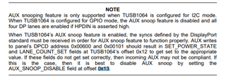
    Sorry about that, This is still possible with TUSB1064 but does I2C access to register 0x13 bit 7 (AUX_SNOOP_DISABLE) through external host or PD controller. 

  • Hi Malik,

    Just had a chance to look into this. so to do things over i2c is a little cumbersome. I did find this note on the datasheet on page 17. Basically sounds like if I'm in GPIO mode then the aux snoop is disabled. So I think it cant be this then since I'm in gpio mode.

  • Hi Carlson,

    Since AUX snoop is disabled it seems the s9 is not negotiating correctly over AUX. Can you measure the AUX_P and AUX_N common mode voltage when the s9 is connected. I do not expect a issue here since negotiation works when multifunction is off but I want to double check. Can you also confirm that signal is present on DP0 and DP1 when the s9 is connected and multifunction is on. This will help narrow down the issue to AUX negotiation for sure. 

  • Malik,

    attached is the signals.

    Multifunction off

    aux negotiated very fast and the display displayed very quickly and then stopped sending data

    DP0 and DP1 were very similar and continued to stream data for ever

    multifunction on

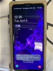
    aux negotiated took a long time and maybe never negotiates but stops negotiating when the hdmi disconnected pops up on the phone even though the cables are no disconnected

    DP0 and DP1 were very similar and continued to stream data until hdmi disconnected appeared 

    auxp auxn multifunction off

    auxp and auxn multifunction off

    auxp and auxn multifunction on

    auxp and auxn multifunction on

    DP0 multiFunction off

    DP0 multiFunction off

    DP0 multiFunction on

    DP0 multiFunction on

  • From your description, it does seems that AUX negotiation is the issue with s9 and multifunction on state. Without the AUX log it is not possible to tell the exact root cause but I do not suspect the lane order issue I mentioned earlier since there is signal present on DP0 and DP1. Lane count mismatch may be the issue here. S9 messaging seems to be related to failure during link training on the DP link which is what were seeing here. Does the S9 enumerate over USB 3? 

  • i currently dont have a method with devkit or our custom board to test this. in both scenarios we don't have usb 3 and i think its a link budget issue. I was wondering though if there is a register in the pd controller to get feedback on when the s9 doesnt connect in multifunction. Basically i was hoping to setup the pd controller in multifunction so that if a s20, or laptop plugs in i will have alt mode and usb3. But when i plug in the s9 i was hoping there is a way to detect the failure to do altmode and then turn off multifunction. currently the few register i check like 0x1a (status), or 0x58 (dp Status) all seem to indicate everything is working

  • From the previous logs I do not think that PD controller will be able to tell something is wrong. Issues here seem restricted to the DP AUX link and link training. Unfortunately TUSB1064 does not have any register to indicate DP link training completion or failure. 

  • ok, and can you think of a way that i could automatically put the S9 in four lane mode when plugged in and then if a s20 or better is plugged in to put it into multifunction. Cause it seems if i put it in multifunction preferred it always does multifunction and if i put it without multifunction it seems to always do four lane display port. 

  • Unfortunately TUSB1064 will not be of much help here. This kind of function would need some GPIO from the DP sink to signal to the PD controller when AUX training has failed. In this case PD controller can perform a hard reset and (if possible) re-negotiate for 4 lane DP. 

  • will the pd controller know when the aux training fails?

  • No, the PD controllers does not decode the AUX bus traffic typically.