This thread has been locked.

If you have a related question, please click the "Ask a related question" button in the top right corner. The newly created question will be automatically linked to this question.

DP83867E: DP83867E Ping Failure at 1500 bytes length.

Part Number: DP83867E

Hi,

We are in production and are facing a throughput issue with DP83867ERGZT part on 50 boards.

We have produced 100# before with no issues.

We might have a different a different set of PCB or a Slightly out of tolerance part due to mfg which we are not 100% sure we have designed for six sigma.

But we have done below so far.

1. When we do small ping packets 64 bytes no issue, 1500 bytes we loose packets during ping.

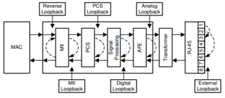
2. Reverse loopback fails

3. Analog loopback using PRBS passes 1500 bytes length

4. External Loopback using PRBS passes 1500 bytes length.

5. I have verified all the basic and external registers and have no clue.

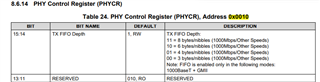
6.TX & RX Delay with shift from clock set to 2ns by register.

7. We are yet to verify the RXFSTS register for SFD or CRC error.

8, Voltage rail with Spec

9. Power on Sequence Correct.

10. XI Clock DC levels correct.

12.When ping with 1500 bytes we saw below.

FALSE_CARRIER_INT (bit 8 of ISR at 0x13),  most of the time is accompanied by a ping failure

IDLE ERROR COUNTER (bits 7:0 of Status Reg at 0xA),most of the time is accompanied by a ping failure

RECR (RECR reg at 0x15), – this changes most prominently and is mostly followed by a ping failure (vice-versa is not always true)


There have been some rare occurrences where ping failed but none of these registers changed, it could also mean that they were just reset automatically before we could read it. Some of these errors occur almost  together. With the current setup, we cannot automate or time/sync the ping failures and the register reads as the microcontroller is connected to the PC only via the debug header.

Question:

1. Where is the Source of PRBS generator, Before or After MII block?

2.We feel the issue is in MII block or TX & RX bath between MAC & PHY as Reverse Fails, Analog Pass ,External Pass. Agree?

3. We are suspecting XI AC characteristics and TX & RX Delay

4. IO_MUX_CFG is 0x0C11 which gives 17ohms on Series Termination, Question is is it for Both RX & TX or only TX Mac pins?

5. Will TDR work in Normal operation, can you little elaborateTi Phy.pdf 

  • Magentics

    and we follow the magnetics recommendation of the datasheet.

    Oscillator part number is ASDMB-25.000MHZ-XY-T

  • Hi Balaji,

    Can you share a block diagram of your design? Can you also read the following registers and tell me their values in both the working and nonworking case:

    • 0x0, 0x1, 0x10, 0x11, 0x31, 0x32, 0x6E, 0x6F

    Can you confirm if any possibly out of tolerance parts are PHY critical, particularly RBIAS?

    I'm looking into your questions and will get back to you with more feedback tomorrow. I'm also reviewing your schematic and will provide feedback by Friday.

    Thanks,

    Lucas

    All information in this correspondence and in any related correspondence is provided “as is” and “with all faults”, and it is subject to TI’s Important Notice (http://www.ti.com/corp/docs/legal/important-notice.shtml).

  •   Bad Good
    0X00 0X1140 0X1140
    0X01 0X796D 0X796D
    0X10 0X7800 0X7800
    0X11 0X0000 0X0000
    0X31 0x10B0 0x10B0
    0X32 0X00D3 0X00D3
    0X6E 0X0000 0X0000
    0X6F 0X0100 0X0100

    There is no difference between them failed and passed board.

    RBIAS resistance is of 1% tolerance 11K value.

    Its 1V stable through the ping tests.

  • Hi Balaji,

    Can you try clearing bit 7 of register 0x31? Please let me know if this helps. Additionally I'm still reviewing your schematic and will provide feedback soon.

    Thanks,

    Lucas

    All information in this correspondence and in any related correspondence is provided “as is” and “with all faults”, and it is subject to TI’s Important Notice (http://www.ti.com/corp/docs/legal/important-notice.shtml).

  • Hi Balaji,

    Here are my notes after reviewing your schematic:

    • The decoupling capacitors on all supplies are different from what's recommended. Each 1nF cap should be replaced with a 1uF cap and 0.1uF cap in parallel. To avoid layout changes, you can stack these capacitors on the footprints of the 1nF caps.
    • I didn't see your isolation between PHY and ERTH GND. This configuration is recommended for best EMC/EMI performance:

    • The 867 doesn't support dual LED function, is this what Q1 is trying to accomplish?
    • Can you confirm your clock meets the datasheet spec? Additionally C427 should be 16pF, not 27pF.
    • I noticed the PU resistor on MDIO is DNP. We recommend a PU between 1.5k and 2.2k, however it seems like you have no issue reading/writing to the registers

    Additionally, can you probe RX_CLK, CLKOUT, and MDI link pulse? Also have you tried clearing bit 7 of register 0x31? Please let me know if this changed anything.

    Thanks,

    Lucas

    All information in this correspondence and in any related correspondence is provided “as is” and “with all faults”, and it is subject to TI’s Important Notice (http://www.ti.com/corp/docs/legal/important-notice.shtml).

  • 1. 

    They are connected like this. I dont think this matters. This is from noise immunity during susceptibility.

    2. The decoupling recommendation is not followed i agree.

    The problem is not the design, we have 100 boards which works in the same condition.

    The recent batch has this kind of issue. 

    Using engineering principles of similarity and isolation technique-this is not the root cause.

    if so why only reverse loopback fails?

    3.Q1 is Do not install, so i wont worry about it.

    4.We have tried bypassing the filtering caps and still have the same issue.

    Except phase noise- we are confident the oscillator meets the phy requirement. We are trying to use an alternate with phase noise spec of 11ps,

    5.MDIO has no pullup externally, but if you see TXS0102DQER onthe sheet it has internal 10K ohms pullup. and the failure is not while accessing MDIO lines

    6. CKOUT follows 25Mhz-i see no issues.

    We have not probed RX_CLK.

    MDI clock pulse is okay.

    7. We have not tried clearing bit 7 of 0x0031 because its same for passing and failing board and the link is at 1gpbs. but we will attempt it.

    8. Can you tell us the source of prbs geneartor?

    9. we need to answer why reverse fails and external passes. thats where the clue is

  • Hi Balaji,

    While I agree that the decoupling can't be the root cause of the issue, I think it's possible it could be a contributing factor and should be something to consider.

    Can you clarify what you mean by bypassing the filtering caps? Do you mean you have tried removing them or have you tried the recommended configuration for 2.5V VDDIO?

    The PRBS generator is located after the PCS block.

    I just want to confirm, you're talking about reverse loopback and external loopback as seen in this figure?

    Thanks,

    Lucas

    All information in this correspondence and in any related correspondence is provided “as is” and “with all faults”, and it is subject to TI’s Important Notice (http://www.ti.com/corp/docs/legal/important-notice.shtml).

  • bypassing the filter caps -> i meant the high pass filter on the oscillator output.

    yes correct i did the external loopback and reverse loopback as in the figure

  • And do you know why RXERR gets updated when i get a failed ping?. 

  • Hi Balaji,

    So by bypassing the filter caps, you mean removing C426 and C427? Please note that when operating at VDDIO = 2.5V, C426 = 27pF and C427 = 16pF are required.

    Can you provide more details about your reverse loopback setup. What is the link partner used? Is the link partner generating packets and counting packets when received again?

    Can you provide more details about your external loopback setup as well. Is the processor generating packets and counting for errors when received back? What is the MAC interface used? Register 0x10 is showing SGMII and a mismatch in RX/TX FIFO depth. Was this intentional?

    Thanks,

    Lucas

    All information in this correspondence and in any related correspondence is provided “as is” and “with all faults”, and it is subject to TI’s Important Notice (http://www.ti.com/corp/docs/legal/important-notice.shtml).

  • So by bypassing the filter caps, you mean removing C426 and C427? Please note that when operating at VDDIO = 2.5V, C426 = 27pF and C427 = 16pF are required.

    Correct. We did this just to verify the dc offset. the VOL was not meet due to the AC coupling.

    Can you provide more details about your reverse loopback setup. What is the link partner used? Is the link partner generating packets and counting packets when received again?

    We sent packets from other network device we designed and count the packets sent and recived.

    Good and Bad boards pass.

    Can you provide more details about your external loopback setup as well. Is the processor generating packets and counting for errors when received back? What is the MAC interface used? Register 0x10 is showing SGMII and a mismatch in RX/TX FIFO depth. Was this intentional?

    Yes external loopback sends packet and receives it and matches the count.

    RGMII is the mac interface(from Broadcom)

    SGMII and RX/TX FIFO depth was not intentional.

    Above is the phase noise and Jitter data.(non working)

    I know that the pHY wants rms phase noise to be <11ps.

    We have the dbC/Hz plot. Can you verify it?

    The reason is, on the failing board we replace the board with different set of oscillator .

    Below is the good oscillator on a working board:

    We could see that the jitter is on the higher end on the non working one but we are unable to make a decision if its the jitter because the phy quotes only RMS phase jitter(phase noise) in ps.

    Can you help?

  • Hi Balaji,

    Based on your statement "RGMII is the mac interface(from Broadcom). SGMII and RX/TX FIFO depth was not intentional," it looks like the issue may be that the PHY is set for SGMII rather than RGMII, as noted by register 0x10, so the MAC is not encoding the correct data. You may refer to Table 2 in the datasheet for instructions on setting RGMII through registers. Else, you may refer to section 8.5 for information on setting RGMII through the hardware bootstraps. 

    Thank you,

    Nikhil

    All information in this correspondence and in any related correspondence is provided “as is” and “with all faults”, and it is subject to TI’s Important Notice (http://www.ti.com/corp/docs/legal/important-notice.shtml). 

  • Its its set to sgmii how do i see data on RGMII?

    And there is no encoding on RGMII, and why does it pass on lower packet size of 64bytes?

  • Hi Balaji,

    We are looking into this question and will provide additional feedback by tomorrow.

    Thank you,

    Nikhil

    All information in this correspondence and in any related correspondence is provided “as is” and “with all faults”, and it is subject to TI’s Important Notice (http://www.ti.com/corp/docs/legal/important-notice.shtml). 

  • Hi Balaji,

    I just want to clarify again, the intended MAC interface is RGMII correct? To return the device to RGMII, please refer to Table 2 in the datasheet. There are two registers that must be set for RGMII: REGISTER 0x0010, BIT 11=0x0 and REGISTER 0x0032, BIT 7 = 0x1.

    Does this allow for correct data to be observed on the MAC side?

    Thank you,

    Nikhil

    All information in this correspondence and in any related correspondence is provided “as is” and “with all faults”, and it is subject to TI’s Important Notice (http://www.ti.com/corp/docs/legal/important-notice.shtml). 

  • Bit 11 of Register 0x0010 is read only BIT. Please give correct register.

    I want you answer my question please.

    1. We could see the failure follow the oscillator. When we change the oscillator the failure goes away. 

    2. Clear bit 7 of register CFG4 (0x0031) per suggestion from TI: RECR register was incrementing (RX errors), so we lost packets

  • Hi Balaji,

    Which datasheet are you referring to? This post references the DP83867E which offers SGMII. Are you using the DP83867E or DP83867IR?

    In regards to your questions:

    1. Does the oscillator meet the datasheet spec for oscillator requirements?

    2. Is this with the new working oscillator?

    Thank you,

    Nikhil

    All information in this correspondence and in any related correspondence is provided “as is” and “with all faults”, and it is subject to TI’s Important Notice (http://www.ti.com/corp/docs/legal/important-notice.shtml). 

  • we are using DP8387E.

    1. we are looking at phase jitter rms which we suspect

    2. The reply has both good and bad.please read it carefully

  • Hi Balaji,

    I'm still not clear on the MAC interface used, is this device intended to be used for SGMII or RGMII? As mentioned above, if the intended MAC interface is RGMII, kindly refer to the DP83867E datasheet and use the settings I have mentioned above.

    In regards to determining if the phase noise is truly the culprit of failures, I have the following suggestions:

    • Can we try an A-B-A swap with units from the initial 100 board build you mentioned has 0 failures? If those known good units start failing, we know it is related to the new board build, and possibly the increase in phase noise.
    • Can we try Ethernet compliance testing? Do you have any capability to perform Ethernet compliance testing? If the PHY on these boards passes the jitter compliance test, there should be no issue. Please refer to this app note for more info on compliance testing: https://www.ti.com/lit/an/snla239b/snla239b.pdf?ts=1631290479260&ref_url=https%253A%252F%252Fwww.google.com%252F

    Thank you,

    Nikhil

    All information in this correspondence and in any related correspondence is provided “as is” and “with all faults”, and it is subject to TI’s Important Notice (http://www.ti.com/corp/docs/legal/important-notice.shtml). 

  • Device used is RGMII. I understand what you are saying.

    You are asking "Bala, you are using RGMII but why do you have 0x0010 bit 11 to 1,which calls it SGMII, you should have it as bit 0"

    I dont why it is set like that but my argument is it wont matter because it works even without it.

    Also we have set 0x032 Bit 7 to 1.

    i will check with the team again on this. May be the phy has intelligence to detect which one is being used apart from the 0x10 and 0x31 and LED0.

    1. We know it is  the new build. that fails.old build works

    2. we are trying to do eth compliance test.

    some info for you.

    Phase Jitter RMS Values
    Faulty board from new batch: 239.4ps
    Good Batch Oscillator: 49ps
    Alternate part from ASDDV series:3.192 ps
    Phy Spec:11ps
  • Sorry i made a mistake is giving the register values:

    The correct ones should be as below:

      Bad Good
    0X00 0X1140 0X1140
    0X01 0X796D 0X796D
    0X10 0X5048 0X5048
    0X11 0xAF02 0xAF02
    0X31 0x10B0 0x10B0
    0X32 0X00D3 0X00D3
    0X6E 0X0000 0X0000
    0X6F 0X0100 0X0100

    And not (red colour is wrong)

    Bad
    0X00 0X1140 0X1140
    0X01 0X796D 0X796D
    0X10 0X7800 0X7800
    0X11 0X0000 0X0000
    0X31 0x10B0 0x10B0
    0X32 0X00D3 0X00D3
    0X6E 0X0000 0X0000
    0X6F 0X0100 0X0100

    I think now the register values are correct, Both 0x10 and 0x31 pointing to RGMII being enabled and sgmii dis enabled

  • Hi Balaji,

    Thanks for the info. We are looking into the register dump and the impact of phase noise and will have additional feedback by Wednesday of this week latest. We appreciate your patience as we try to drive towards a working solution.

    Thank you,

    Nikhil

    All information in this correspondence and in any related correspondence is provided “as is” and “with all faults”, and it is subject to TI’s Important Notice (http://www.ti.com/corp/docs/legal/important-notice.shtml). 

  • Hi Balaji,

    Apologies again for the need to clarify, but earlier in this post there was a claim that changing the oscillator allowed the boards to work? When using a "good" oscillator were there still issues?

    The additional phase noise of the oscillator could definitely be a factor in PHY performance.

    Thank you,

    Nikhil

    All information in this correspondence and in any related correspondence is provided “as is” and “with all faults”, and it is subject to TI’s Important Notice (http://www.ti.com/corp/docs/legal/important-notice.shtml). 

  • no issues when using a good oscillator which had phase noise of 49ps even though the phy told its is 11ps.

    Problem occurs when we use a oscillator which has phase noise of 239ps.

    can you tell what exactly will get affected because of phase noise?

    I know period jitter pk-pk affects the setup and hold margin but could not think of what is inside the phy

  • Hi Balaji,

    The XI clock is the reference clock for PHY, so jitter in this clock results in jitter for transmit and receive clocks of the PHY as well as a degraded SNR.

    Does this answer your question?

    Thank you,

    Nikhil

    All information in this correspondence and in any related correspondence is provided “as is” and “with all faults”, and it is subject to TI’s Important Notice (http://www.ti.com/corp/docs/legal/important-notice.shtml).

  • can you elaborate a little more.. please tell me numbers. what margin am i violating if have 49ps instead of 11ps? Ethernet phy validation test? SNR Of what? RGMII side or Differential ethernet side?. What is the SNR of the Ethernet Differential Signal? SNR Of Digital bits is not applicable because its not modulated and is VIH-VOH or VOL-VIL =noise margin and clocks dont affect it.. 

  • Hi Balaji,

    This will affect the MDI signaling. Though our datasheet specs 11ps jitter, you seem to be ok with your clock having 49ps, correct? Some tests you may conduct on the transmitter end are the IEEE PMA Compliance tests, particularly the jitter tests. If all tests are passing, there may be no issues on the transmit side. To check the receiver side, you may do a link up test.

    Please let me know if you have any further questions.

    Thank you,

    Nikhil

    All information in this correspondence and in any related correspondence is provided “as is” and “with all faults”, and it is subject to TI’s Important Notice (http://www.ti.com/corp/docs/legal/important-notice.shtml).

  • Can you share EEE PMA Compliance tests?

  • And can you share link up tests as well?

  • Hi Balaji,

    You may refer to the Tektronix TDSET3 Ethernet Compliance Test Software manual. This is the test suite we have used in the past. The connections and setup instructions for the jitter test are described in this manual. You may also refer to our app note How to Configure DP838xx for Compliance Testing for additional info including the register scripts for each compliance test mode.

    For the link test, you may simply connect a cable and poll register 0x1 to confirm linkup.

    Thank you,

    Nikhil

    All information in this correspondence and in any related correspondence is provided “as is” and “with all faults”, and it is subject to TI’s Important Notice (http://www.ti.com/corp/docs/legal/important-notice.shtml).

  • Hi Balaji,

    I believe I shared the Compliance test setup we have used in our lab in my previous post, as well as the simple link test instructions. Was there any other information requested?

    Thank you,

    Nikhil

    All information in this correspondence and in any related correspondence is provided “as is” and “with all faults”, and it is subject to TI’s Important Notice (http://www.ti.com/corp/docs/legal/important-notice.shtml).

  • Hi Balaji,

    I am covering for nikhil,

    Is there any additional input you need from our side.

    Regards,

    Sreenivasa

  • Hello Balaji, 

    Should i go ahead and close the thread?

    Regards,

    Sreenivasa

  • Hello Balaji, 

    I have not heard from you, do you have some inputs. If not can you please close the thread as resolved.

    Regards,

    Sreenivasa

  • Hello Balaji, 

    Could you please close the thread by clicking the resolved button.

    Regards,

    Sreenivasa

  • Hello Balaji, 

    I am going ahead and closing the tread.

    Regards,

    Sreenivasa