This thread has been locked.

If you have a related question, please click the "Ask a related question" button in the top right corner. The newly created question will be automatically linked to this question.

TPS25750: Battery charging issue

Part Number: TPS25750
Other Parts Discussed in Thread: BQ25792

Hi

I am struggling with the battery charging issue when the v7.0.2 for Application Customization Tool used.

The bundle binary generated by v7.0.1 had no that issue, but it had the bug related to I2Cr task instead.

See below please.

My Configurations:

{"questionnaire":{"version":"7.0.2.1","answers":[4,null,2,1,0,0,1,null,1,null,0,12.6,0.8,0.2,0.12],"options":{},"configID":"0000","vendorID":"0000"}}

tps25750_config_20210818.zip


Test Environments

No evalutation board(EVM). But I tested with my sample board included TPS25750 and BQ25792.

Application Customization Tool v7.0.2 used.

PBMs was used to patch the bundle data. It was successful.

Symptoms:

There is no issues related to I2Cr and I2Cw but no longer charging battery.

But battery was charged well in default even without any settings when the patch bundle after generating with the previous version 7.0.1 was downloaded successfully.
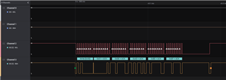
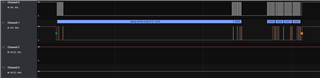
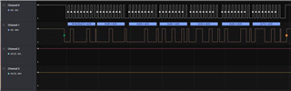
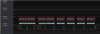

Captured:

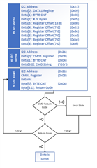
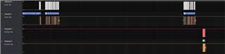
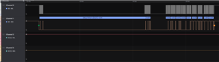
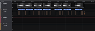
I2Cm_SCL and I2Cm_SDA lines

captured.zip


Questions:

- Should I write the Full Flash Binary on my test board to use things of the version 7.0.2 ? I used to use the Low Region Binary until now.

If so, how to do that?

  • 0647.captured#2.zip

    I attached a new captured. Ignore the above captured.zip.

  • One more thing for your information.
    When I read the REG0A_Re-charge_Control Register of the BQ25792.

    In battery power only, I could read the value, 0xA3. It seems to work correctly.
    But if battery supplied with DC power, I could read 0x00 for the REG0A_Re-charge_Control Register at the BQ25792.

    It seems that something(TPS25750?) makes the BQ25792 to be mis-behavior.

  • JK,

    I am reviewing the GUI changes between7.01 and 7.02 to see if something was inadvertently changed that caused this issue.

    Regards,

    Chuck

  • It seems that I2Cw is not working.
    I had written 0x02 at the REG11_Charger_Control_2 Register. The 0x02 means Shutdown Mode as you know.
    Below are my logs.

    ========= Read: to check default value. 0x00 returned.
    [ 4.736996@1] tps25750: Read(I2Cr) slave - addr: 0x6b, reg: 0x11
    [ 4.737769@1] tps25750: num: 3
    [ 4.738144@1] hexdump:
    [ 4.738458@1] 6B 11 01
    [ 4.738772@1] tps25750: Write DATA1
    [ 4.757779@1] tps25750: Write I2Cr on CMD1
    [ 4.797754@1] tps25750: Read CMD1
    [ 4.817754@2] tps25750: CMD1 ret: 0x0
    [ 4.837748@1] tps25750: Read DATA1:
    [ 4.842176@1] hexdump:
    [ 4.842190@1] 00 00 00 00 00 00 00 00 00 A5 2F 95 F4 8F D1 21
    [ 4.842616@1] AD 06 80 28 00 05 09 F5 01 03 00 01 F1 03 00 00
    [ 4.843439@1] D1 8D 29 5A D1 8D 29 5A 00 00 00 00 00 00 00 00
    [ 4.844263@1] 00 00 00 00 00 00 00 00 00 00 00 00 00 00 00 00
    [ 4.845086@1] tps25750: Task result: 0x0
    [ 4.845585@1] tps25750: Task completed successfully.
    [ 4.846280@1] tps25750: out: 0x0

    ========= Write: 0x02.
    [ 4.865769@1] tps25750: Write(I2Cw) slave - addr: 0x6b, reg: 0x11
    [ 4.865847@1] tps25750: num: 5
    [ 4.866234@1] hexdump:
    [ 4.866548@1] 6B 01 00 11 02
    [ 4.866949@1] tps25750: Write DATA1
    [ 4.885769@1] tps25750: Write I2Cw on CMD1
    [ 4.925805@1] tps25750: Read CMD1
    [ 4.945778@1] tps25750: CMD1 ret: 0x0
    [ 4.965792@2] tps25750: Read DATA1:
    [ 4.970196@1] hexdump:
    [ 4.970213@1] 00
    [ 4.970223@1] tps25750: Task result: 0x0
    [ 4.970565@1] tps25750: Task completed successfully.

    ========= Read: One more reading to check whether it returns 0x02 or not.
    [ 4.989780@2] tps25750: Read(I2Cr) slave - addr: 0x6b, reg: 0x11
    [ 4.989846@1] tps25750: num: 3
    [ 4.990234@1] hexdump:
    [ 4.990549@1] 6B 11 01
    [ 4.990862@1] tps25750: Write DATA1
    [ 5.009778@1] tps25750: Write I2Cr on CMD1
    [ 5.049781@1] tps25750: Read CMD1
    [ 5.069793@1] tps25750: CMD1 ret: 0x0
    [ 5.089809@1] tps25750: Read DATA1:
    [ 5.094341@1] hexdump:
    [ 5.094600@1] 00 00 00 00 00 00 00 00 00 A5 2F 95 F4 8F D1 21
    [ 5.095422@1] AD 06 80 28 00 05 09 F5 01 03 00 01 F1 03 00 00
    [ 5.096246@1] D1 8D 29 5A D1 8D 29 5A 00 00 00 00 00 00 00 00
    [ 5.097069@1] 00 00 00 00 00 00 00 00 00 00 00 00 00 00 00 00
    [ 5.097917@1] tps25750: Task result: 0x0
    [ 5.098391@1] tps25750: Task completed successfully.
    [ 5.099052@1] tps25750: out2: 0x0

  • JK,

    I will review these results later today to see if I can see any issue.  

    This format is ideal for me to debug with.

    Thanks,

    Chuck

  • Hi Chuck, thank you for your kind reply.

    Today, I received a very angry call from my customer.
    He didn't believe why TI has the issue like thing and had threatened that can cancel this project.
    But I hope this project is to be continued.

    Could you give quick response?

  • I was out of the office on PTO for a few days.  I apologize for the delay in response.


    Here is an example of how to use the I2Cw command:

    Here is a sequence and set of screen captures for the I2Cw command being executed on the EVM.  The top 2 traces are the I2Cs bus and the bottom two traces are the I2Cm bus:

    From my look at their logs, they might also be having an issue with the I2Cr command.  If this is the case, then I can capture the same sequence for the I2Cr command.

    Please let me know.

  • Here are captures of the I2Cr command for your reference as well:

    Data 1 register

    Command Register

    I2C read from the I2Cm bus:

    The command result was correct, but I did not save it off in the tool that I had on hand.

  • Hi Chuck,

    Thanks for kind descriptions.

    The above my logs for REG11_Charger_Control_2 Register seems not enough to understand you. So I attach a new log file to help you.

    REG11_Charger_Control_2 testing in battery mode.
    
    #######################
    # Read REG11_Charger_Control_2. It returns 0x00
    
    [   12.639032@1]  tps25750: BQ25792 TEST ======================= Start
    [   12.639812@1]  tps25750: [BQ_TEST, 1568] Start (Charger Control 2)
    [   12.640844@1]  tps25750: Read(I2Cr) slave - master(TPS): 0x21, slave(BQ): 0x6B, reg: 0x11, numToRead: 1
    [   12.642048@1]  tps25750: Write DATA1
    [   12.642457@1]  tps25750: Write addr: 0x21, reg: 0x09
    [   12.643074@1]  tps25750: numToWrite: 3, data: 
    [   12.643626@1]  6B 11 01 
    [   12.661581@1]  tps25750: Write 'I2Cr' on CMD1
    [   12.661610@1]  tps25750: Write addr: 0x21, reg: 0x08
    [   12.662049@1]  tps25750: numToWrite: 4, data: 
    [   12.662602@1]  49 32 43 72   
    [   12.681620@1]  tps25750: Read CMD1
    [   12.701608@1]  tps25750: CMD1 ret: 0x00
    [   12.721600@1]  tps25750: Read DATA1: 
    [   12.726083@1]  tps25750: Task completed successfully. ret: 0x00
    [   12.726129@1]  tps25750: read BQ reg(0x11) value: 0x00
    
    #######################
    # Write REG11_Charger_Control_2 with 0x02. 
    
    [   12.745620@1]  tps25750: Write(I2Cw) slave - master(TPS): 0x21, slave(BQ): 0x6B, reg(BQ): 0x11, data: 0x02, numToWrite: 1
    [   12.746294@1]  tps25750: Write DATA1
    [   12.746739@1]  tps25750: Write addr: 0x21, reg: 0x09
    [   12.747353@1]  tps25750: numToWrite: 5, data: 
    [   12.748089@1]  6B 01 00 11   02 
    [   12.765591@1]  tps25750: Write 'I2Cw' on CMD1
    [   12.765619@1]  tps25750: Write addr: 0x21, reg: 0x08
    [   12.766060@1]  tps25750: numToWrite: 4, data: 
    [   12.766613@1]  49 32 43 77   
    [   12.785580@1]  tps25750: Read CMD1
    [   12.805609@1]  tps25750: CMD1 ret: 0x00
    [   12.826365@1]  tps25750: Read DATA1: 
    [   12.831556@1]  tps25750: Task completed successfully. ret: 0x00
    
    #######################
    # Read REG11_Charger_Control_2 again. I guessed it would turn 0x02, but it was 0x00.
    
    [   12.849601@1]  tps25750: Read(I2Cr) slave - master(TPS): 0x21, slave(BQ): 0x6B, reg: 0x11, numToRead: 1
    [   12.850079@1]  tps25750: Write DATA1
    [   12.850526@1]  tps25750: Write addr: 0x21, reg: 0x09
    [   12.851139@1]  tps25750: numToWrite: 3, data: 
    [   12.851692@1]  6B 11 01 
    [   12.869614@1]  tps25750: Write 'I2Cr' on CMD1
    [   12.869646@1]  tps25750: Write addr: 0x21, reg: 0x08
    [   12.870084@1]  tps25750: numToWrite: 4, data: 
    [   12.870636@1]  49 32 43 72   
    [   12.889579@1]  tps25750: Read CMD1
    [   12.909586@1]  tps25750: CMD1 ret: 0x00
    [   12.929610@1]  tps25750: Read DATA1: 
    [   12.934078@1]  tps25750: Task completed successfully. ret: 0x00
    [   12.934125@1]  tps25750: read BQ reg(0x11) value: 0x00
    [   12.953591@1]  tps25750: [BQ_TEST, 1583] End (Charger Control 2)

    I think I2Cr, I2Cw functions are no problem as like above log file.


    Anyway.

    Let's think about regarding to the I2Cr, I2Cw after solving the issue unable to charge battery.

    As I mentioned the Symptoms in above.

    Battery is not charged in v7.0.2 when I plug DC power.

    It charged well in v7.0.1 by default.

    Could you solve it first please as soon as possible?

    PS:

    Chuck, could you let me your time zone? I want to support you in real time if it is possible.

  • JK,

    I am in the US Central time zone.

    I have reviewed the changes made from the 7.01 GUI to the 7.02 GUI and none of them were expected to impact the charger.  

    Are you able to monitor the I2C bus that connects the I2Cm of the TPS25750 to the BQ25792?  

    I would like to be able to review the control traffic between the two devices in your system and compare it to one of our reference designs.  I do not have the equipment to mimic a battery easily accessible to me, so the best I can do is review the control traffic between the 2 parts to see what has changed between the 2 revisions.  

  • JK,

    I am working with the GUI developer and the firmware team to look into what is happening here, but I do not have any current updates today.

    I have a Reference design in my possession to test with, but do not currently have it up an running.  I will be working on this first thing tomorrow morning.

    Regards,

    Chuck

  • Hi Chuck,

    I attached some captured data to I2C signal. See below please.

    If you don't mind, I would like to send and receive feedback in real time by extra communication channel like skype, etc.
    My skype ID: linorise0904
    So I'm sure I can send immediately that you need things.

    It's really urgent to me so I ask you.

    Battery Charging Issue by 7.0.2 v02.xlsx

  • Hi Chuck,

    How can I do that TPS25750 and BQ25792 working separately?

    I would like to access BQ25792 directly from CPU(host).

    Actually I was able to access BQ25792 directly after isolating pysically from TPS25750.
    But bundle patch download procedure(PBMs) of TPS25750 is generating a problem.
    It makes device reboot.

    In PBMs procedure needs a slave address like BQ25792 address.
    I think it is because TPS25750 trys to write budle patch to BQ25792.
    But BQ25792 is isolated pysically from TPS25750 as I mentioned above.

    In conclusion, I hope I can download patch bunlde only for TPS25750 without regardless of BQ25792.
    And I want to access BQ25792 registers from cpu(host).

  • JK,

    The patch bundle should be loaded on the I2Cs.  The charger interface is on the I2Cm bus, so there should be no contention.

    The method that we recommend to control the BQ25792 is the use the I2Cw and I2Cr commands to access it through the TPS25750.  This would give you independent control of the ICs.

    I am currently debugging the issue that you are having because I feel that it is related to other customers as well.  I should have an update for you in a few hours.

    Regards,

    Chuck

  • JK,

    I have confirmed that we have introduced a bug in the 7.02 GUI that we are working to patch currently.

    I will update you once I have a new GUI release tested.  

  • HI Chuck,

    I hope to get the new GUI release asap.

    I appreciate your efforts.

  • I will keep you updated.  I am now testing a very early version.

  • Very good news.

  • JK,

    We are going to perform electrical load testing with the latest version of our code and may be able to provide you with an early release for your customer on Monday.

    Please send me a direct email by looking me up internally and I can work with you on Monday to resolve this issue as soon as possible

    Regards,

    Chuck

  • Hi Chuck,

    Good.

    I didn't find your email address, but I think I can get it from TI Korea.

    And if I have a problem, I will send you to your email.

    I look forward on Tuesday.

    I appreciate you and your great team.

    Thanks,

    JK

  • I am happy to help.  I will keep this open until the 7.03 GUI is releaed

  • Hi Chuck,

    How is it going V7.0.3?
    You said that you seem to be able to release the v7.0.3 early this week.

    JK

  • JK,

    We are addressing an issue that came up in testing.  We do not have everything working 100% reliably as of right now.

    I will keep you posted as we make progress.

    Regards,

    Chuck

  • Hello,

    Is this still in process?

  • We are in the final stage of testing right now. 

  •   I'm waiting on the new GUI & Firmware for this TI chip combo also. Were you able to get things working via some other method yet or did you move on to a different solution? 

    What was wrong with the Firmware 7.0.1 that was working as far as charging?

  • Ryan,

    The 7.01 firmware did not set the IINDPM and VINDPM correctly to prevent the charger from taking more current than the source could provide.  It also had issues with configuring the VOTG and IOTG.

    The upcoming firmware addresses both of these issues.

  • Hello,

    Is this still in process?

  • Chong Yu,

    We have fixed the firmware, but our GUI release is not yet ready.

    I will prepary a binary file for you based on the provided configuration tomorrow.

  • Hello,

    Is this still in process?

  • Chong,

    We have been addressed issues in internal testing and will release the GUI as soon as the testing is completed