Hii,
I want to use DP83869HMRGZT in SGMII to RGMII bridge mode
What is the recommendation for TD_P/M pins in this mode?
This thread has been locked.
If you have a related question, please click the "Ask a related question" button in the top right corner. The newly created question will be automatically linked to this question.
Hello ranjini r
Thank you for the Query.
If you could provide some additional details on the requirements that would help.
I will assume you are asking what care to take on the SGMII signals.
The SGMII signals need to be AC coupled and have to be placed near to the receiver.
If any of the differential signals have straps, similar dummy straps have to be placed on the other line
Treat them as differential lines during the design.
Regards.
Sreenvasa
Hi,
Can u please have a look at the attached design & suggest if any changes are to be made?
I have connected 3.3V as VDDIO, does it support the required configuration?ETH_RGMII to SGMII.pdf
Hello Ranjini,
Thank you for the inputs. I will review.
Did you not place the AC caps for the SGMII - i did not see them in the schematics.
I have connected 3.3V as VDDIO, does it support the required configuration - please explain what you meant.
Regards,
Sreenivasa
Hello Ranjini,
Thanks you for the inputs and no worries.
Please note that the AC caps must be placed near to the receiver - meaning the input caps must be near to the PHY.
I will review and provide my inputs by Wednesday.
Regards,
Hello Ranjini,
Please find attached.
I assume this a RGMII to 100Base-FX module.
Regards,
Sreenivasa
Hello Ranjini,
Thank you for letting me know. Looks good.
Regards,
Sreenivasa
Hello Ranjini,
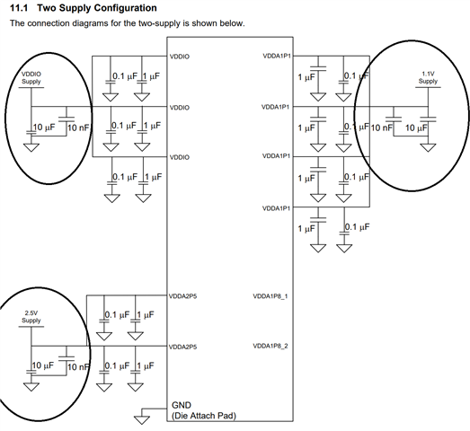
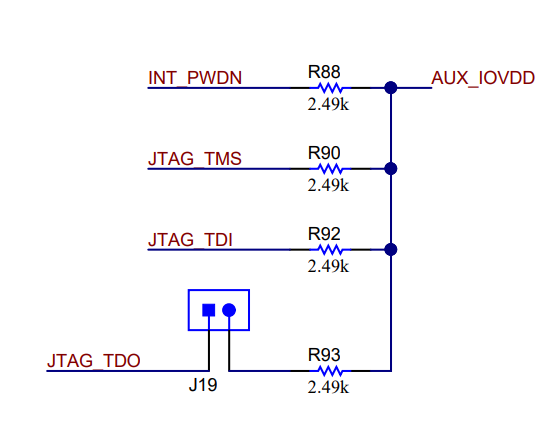
Please see below for supply decoupling and JTAG. Place a 33 pF parallel to the RBIAS resistor (R429). This improves device performance specifically during compliance testing.
.
Regards,
Sreenivasa
Hello,
Thank you for the inputs.
I'm using 2 DP83869HM. In RGMII to Copper & RGMII to SGMII bridge mode (the feedback points are implemented)
Can you please have a look at the attached design.
Regards,
Ranjini.R7673.ETH.pdf
Hello Ranjini,
Thank for sharing the schematics.
I did a quick review to support the project timeline,
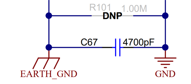
I have embedded the comments in the schematics. Placing a cap between shield and the circuit ground as shown below is recommended. A mounting hole to connect the shield to external ground is also recommended.
Regards,
Sreenivasa