This thread has been locked.

If you have a related question, please click the "Ask a related question" button in the top right corner. The newly created question will be automatically linked to this question.

DS90UB953-Q1: Request 953 Circuit Review

Part Number: DS90UB953-Q1

Hi there

I'm a South Korean Automotive camera engineer. 

Please review the DS90UB953-Q1 circuit.

We are planning to use Non Sync Mode. Therefore, an external oscillator was added.

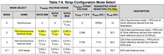
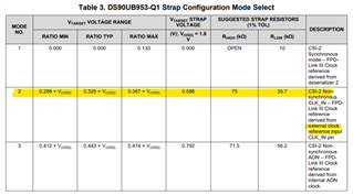
10k and 4.7k were adopted as Strap Configuration Mode resistance, and 5% resistance will be used.

I added a table below that calculates the mode pin input voltage using 10k and 4.7k.

Max 0.615
Typ 0.576
min 0.537

And, I didn't add ferrite beads to the poc line, should I?

Additionally, we use MIPI 4 Lane.

Please refer to the attached circuit as well.

TI_REQUEST.pdf

Thank You!

  • Hello Choi,

    I can review your schematic. The typical timeline for a Schematic Review is ~1 week, so I will return with to this post with full comments by (10/8) at the latest.

    And here are some responses for your concerns so far,

    1) Yes, in Non-Sync Mode, the Serializer will need an external oscillator.

    2) For the MODE pin, the selected strap-resistors are fine. You just need to create a voltage divider that outputs a voltage within the voltage range of the mode that is desired. We normally suggest 1% tolerance resistors for a tighter range, but it is not required. Your 10k-Ohm pull-up resistor and 4.7k-Ohm pull-down resistor with 5% tolerance do match the voltage range for Non-Synchronous External Clock mode, highlighted below.

    3) The PoC circuit does match the example in the UB953 datasheet and does include Ferrite Beads (BLM18HE152SZ1) in the design. Could you elaborate on what you mean by adding more Ferrite Beads to the PoC line?

    Also, since the design from the datasheet is being used, make sure that the current through the PoC network is <=150mA. DC bias current can affect the impedance characteristics of the Ferrite Beads used in the PoC network and reduce the needed impedance at the channel's operating frequency.

    Best,

    Justin Phan

  • Thank you for your answer.

    POC power passes through the POC filter and is connected to the PMIC, which means one Ferrite Bead in between.

  • Hi Choi,

    As long as the PoC network meets the impedance requirements at the channel Nyquist frequency and at the given DC bias current, then there should be no issues. An additional Ferrite Bead between the PoC Network and the PMIC is not required by TI. Our UB953 EVM feeds the PoC voltage to a Step-Down Switching Voltage Regulator, with no extra Ferrite Beads in between the PoC network and the voltage regulator. 

    Best,

    Justin Phan

  • Hi Choi,

    I have finished my Schematic Review. Attached is a PDF with my comments. Let me know if you have any questions.

    TI_REQUEST_Reviewed.pdf

    Best,

    Justin Phan