This thread has been locked.

If you have a related question, please click the "Ask a related question" button in the top right corner. The newly created question will be automatically linked to this question.

DS90UB953-Q1: 953 clock mode

Part Number: DS90UB953-Q1

Hi Expert,

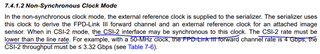
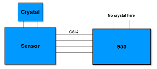
For the 953 and sensor connection, for one use case, if sensor use external clock from crystal X1 and 953 also use external clock from another crystal X2. The MIPI input clock from sensor to 953 is based on the crystal X1. for the 953, which clock will 953 use as reference clock ? crystal X2 or MIPI input clock from crystal X1?

Best regards,

Huang

  • Hello Huang,

    The 953 does not use the MIPI CSI-2 clock as the reference clock. It can only use the external reference attached to the CLKIN pin or it can use the back channel from the remote deserializer as the reference clock when operated in synchronous mode. 

    Best Regards,

    Casey 

  • Hi Casey,

    Thanks for your quick response. If 953 don't take MIPI CSI-2 clock as the reference clock,  use CLKIN pin as reference,

    1. The CLKIN is 25MHz, how does this reference clock adapt to the pixel clock of different resolution image?

    2.If MIPI CSI-2 clock  and CLKIN not sync, need to a buffer/FIFO for the MIPI input. If the FIFO overflow or underflow, how does the 953 to react to the FIFO overflow or underflow to make the system work normally?

    Thanks

    Best regards,

    Huang

  • Hello Huang,

    There is no synchronization needed between the CLKIN and the CSI-2 input clock within 953. The CLKIN is used to source the clock domain for the FPD-Link transmitter in non-synch mode which operates at a fixed rate of CLKIN*160. So for 25MHz CLKIN, the FPD-Link FC works at 4Gbps. The CSI-2 input data is clocked in at whatever rate is provided based on the CSI-2 input clock and there is no configuration needed in the 953 to support different input rates between 80-800Mbps/lane. If the FIFO is underflowed, then the FPD-Link just sends idle characters automatically. If the FIFO is overflowed, then the 953 will drop data going to the output causing partial packets or missing packets which can be detected on the deserializer side. That only happens when the 953 is given CSI-2 input at higher speed than the datasheet allows (in this case > 800Mbps/lane) 

    Best Regards,

    Casey 

  • Hi Casey,

    Thanks for you detail feedback. Think already understand your meaning. There is a state in DS"the CSI-2 interface may be synchronous to this clock", maybe there is some misunderstanding of the statement.

    Go through the datasheet, it showed that the CSI-2 throughput should be less than the FPD throughput . So underflow is more easier happen than the overflow.

    Also for the non-sync mode with external clock, another problem is that for the 954 side, the 954 CSI-2 Tx use 954 side crystal as reference clock.So the  953 side CSI-2 input is based on the CSI-2 clock of of 953 side, which have a relationship with the pixel clock,  while the CSI-2 Tx PLL of 954 use the reference clock from 954 XIN/REFCLK pin.

    If the CSI-2 input clock of of 953 side  and XIN/REFCLK of 954 have a small frequency deviation, the Video Buffers in 954 side is easy to overflow or underflow? how to make the FIFO sync back to half? 

    Thanks

    Best regards,

    Huang

  • Hello Huang,

    The CSI-2 interface may be synchronous to the CLKIN but it does not have to be. They can also be completely a-synchronous so long as the max data rate limitations are observed. The CSI-2 clock on the 953 side also does not need to be the same as the CSI-2 clock on the 954 side. The 954 side speed/bandwidth based on the lane count and lane speed just needs to be greater than or equal to the input rate at the 953 side to prevent an overflow condition. The lane count and lane speed are programmable in the 954

    When there is no available data to forward from the 954 side, then the CSI-2 interface will idle in LP-11 which is the standard implementation of CSI-2 data transmission. There is no concern for underflow

    Best Regards,

    Casey 

  • Hi Casey,

    Thanks for you continuous feedback. two more questions:

    1. For one use case:

    sensor CSI-2 Tx->CSI-2 Rx->FIFO->Link

    If the Tx speed configure to 1.5Gbps, and 953 configure to 2G mode, two questions:

    A. 953 CSI-2 data lane is 932 Mbps/lane, can it connect to sensor 1.5Gbps/lane output?

    B. If CSI-2 Tx configure to 1.5Gbps or 932Mbps, the  acutual payload is 2Gbps from sensor, so there are 0.932*4-2G=1.6Gbps idle data in the MIPI interface,

    while these idle data will come into the FIFO, how to hanle this to avoid the overflow?

    2.  Clock mode

    For below use case, non-sync, 953 have no crystal while sensor have crystal, does this setup work or not?

    Thanks

  • Hello Huang,

    The 953 has a maximum supported MIPI rate of 832Mbps/lane and can not accept any higher rate under any condition. It can not work with 932 or 1.5Gbps/lane. 

    #2 can work if the 953 is used in sychronous mode with a compatible deserializer. There is no need for synchronization between the sensor clock domain and the serializer clock domain 

    Best Regards,

    Casey 

  • Hi Casey,

    Thanks for your feedback. Clear about the situation. one more question about 954, for the 954 side, there are also a FIFO in 954. The 954 CSI-2 Data Rate Scalable for 400 Mbps / 800 Mbps / 1.5 Gbps / 1.6 Gbps :

    1. 953-954 LINK configure as 4.2Gbps, if the 954 output data rate configure as the 800MBPS, so the total CSI output data rate is 3.2Gbps, The FIFO will overflow

    2.953-954 LINK configure as 4.2Gbps, if the 954 output data rate configure as the 1.5GBPS, so the total CSI output data rate is 6Gbps, The FIFO will underflow

    So for above two use cases, how the 954 internal operate to avoid such problem?

    Thanks

    Best regards,

    Huang

  • Huang,

    This is not correct. On the 954 side, the CSI-2 rate just needs to be >= to the CSI-2 rate at the input of the 953 serializer. It is not directly related to the link rate 4.2Gbps since that is the FPD link rate and includes FPD coding/other information which does not get forwarded on the CSI-2 bus. The FIFO will overflow if the input rate on the 953 side is > the output rate on the 954 side. 

    However any idle time where there is no available data to send from the 954 CSI-2 output transmitter is spent in LP11 idle state so the 954 output rate can be much faster than the CSI-2 input rate on the 953 side without any concern of FIFO underflow. That is the standard method for CSI-2 transmission. 

    Best Regards,

    Casey 

  • Hi Casey,

    Clear about this topic not related to FPD data rate.

    Let me summarize :

    1.   954 output CSI data rate configure as the 800Mbps, 953 input CSI data rate configure as the 600Mbps:

    there will be no underflow as you metioned in last replay.  "However any idle time where there is no available data to send from the 954 CSI-2 output transmitter is spent in LP11 idle state so the 954 output rate can be much faster than the CSI-2 input rate on the 953 side without any concern of FIFO underflow. That is the standard method for CSI-2 transmission. "

    Is my understanding correct?

    2. 954 output CSI data rate configure as the 600Mbps, 953 input CSI data rate configure as the 800Mbps

    What about the FIFO status at the same? Will the FIFO overflow? how to handle the FIFO overflow?

    Thanks

    Best regards,

    Huang

  • Huang,

    1.   954 output CSI data rate configure as the 800Mbps, 953 input CSI data rate configure as the 600Mbps:

    there will be no underflow as you metioned in last replay.  "However any idle time where there is no available data to send from the 954 CSI-2 output transmitter is spent in LP11 idle state so the 954 output rate can be much faster than the CSI-2 input rate on the 953 side without any concern of FIFO underflow. That is the standard method for CSI-2 transmission. "

    Is my understanding correct?

    Yes this is correct 

    2. 954 output CSI data rate configure as the 600Mbps, 953 input CSI data rate configure as the 800Mbps

    What about the FIFO status at the same? Will the FIFO overflow? how to handle the FIFO overflow?

    Yes this will cause a FIFO overflow. You need to increase the 954 output CSI-2 rate to prevent an invalid configuration like this. (But also note there is no 600Mbps/lane output rate for 954. The 954 supports 400Mbps/lane, 800Mbps/lane, and 1600Mbps/lane speeds

    Best Regards,

    Casey 

  • Hi Casey,

    OK Thanks

    For the second scenario:

    If set 954 output CSI data rate configure as the 800Mbps, 953 input CSI data rate configure as the 800Mbps. They are equal.

    My question is:

    the 953 input speed is from the oscillator of the Sensor, can call it X1

    the 954 output speed is from the oscillator of the 954, can call it X2

    Often the requirement for the oscillator is 100ppm, if the X1 and X2 in opposite direction.

    For instance, 953 input = 800Mbps+100ppm and 954 output= 800Mbps-100ppm, how to handle this case?

    Best regards,

    Huang

  • Hello Huang,

    This should not cause a problem because 954 has idle time available after each active video line where the lanes go to LP11 and no data is sent. If the 953 line readout is slightly faster than the 954 line readout, then the 954 will just spend slightly less time in LP11 after each video line compared to 953 input to compensate the difference. 954 buffers a full line before sending out anyways

    Best Regards,

    Casey 

  • Hi Casey ,

    Thanks for you reply. Let me understand your description.

    1. "954 has idle time available after each active video line where the lanes go to LP11 and no data is sent"

    Could you help describe how the idle time works?

    2. "If the 953 line readout is slightly faster than the 954 line readout, then the 954 will just spend slightly less time in LP11 after each video line compared to 953 input to compensate the difference. 954 buffers a full line before sending out anyways"

    Who control the LP11 of 954 to make sure the time is slightly less than 953?

    Also what is the size of 954 buffer? how to determine the 954 buffer size, does it impact the LP11 time?

    Best regards,

    Huang

  • Hello Huang,

    1. "954 has idle time available after each active video line where the lanes go to LP11 and no data is sent"

    Could you help describe how the idle time works?

    This is the standard operation of CSI-2. Each video line is separated by LP-11 idle time. I would suggest to study the MIPI CSI-2 standards doc for detailed level info about how the CSI-2 protocol sends data 

    2. "If the 953 line readout is slightly faster than the 954 line readout, then the 954 will just spend slightly less time in LP11 after each video line compared to 953 input to compensate the difference. 954 buffers a full line before sending out anyways"

    Who control the LP11 of 954 to make sure the time is slightly less than 953?

    Also what is the size of 954 buffer? how to determine the 954 buffer size, does it impact the LP11 time?

    This is automatic - there is no need to control this operation manually. The 954 buffer size is 16kB for each RX port. The buffer size does not impact LP-11 time

    Best Regards,

    Casey 

  • Hi Casey,

    Thanks for you feedback. Sorry for bother you again.

    For the 933 OUT+ mode, datasheet state CML, my question is that why not use VML, the power consumption of VML is 1/4 of CML under same speed?

    Best regards,

    Huang

  • Huang,

    The design and inner working of the analog FPD-Link device is TI proprietary - is there any remaining technical support that you need on this product in order to implement a design with the part? That is the main purpose of this forum. Not to discuss alternative ways to design an IC 

    Best Regards,

    Casey 

  • Thanks and Understanding.