This thread has been locked.

If you have a related question, please click the "Ask a related question" button in the top right corner. The newly created question will be automatically linked to this question.

TUSB2046I: [TUSB2046IBVF] Schematic review and inquiries and requests

Part Number: TUSB2046I
Other Parts Discussed in Thread: MAX3232

Hi, TI Support Team

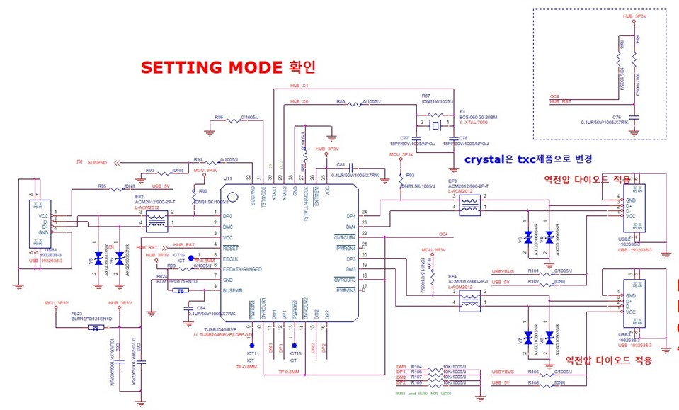
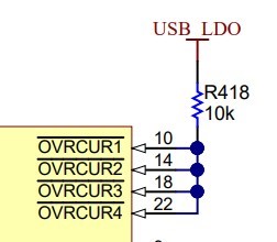
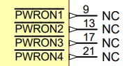
A request for schematic review has been received from a customer.

USB&EXT.pdf

In addition, inquiries and requests have been received.

1. Check if there is a plan to discontinue parts within 5 years

2. Request confirmation of conformity of design

3. If there is a product with a simpler package, request a replacement product recommendation

4. Request hardware design guide material

Please, reply.

  • Hi,

    There are several necessary components missing. Please refer to figure 11 in the datasheet to update the schematic. 

    1. There is no plan to discontinue this part at this time.

    2. Design missing serval components on the upstream port and and downstream ports for proper operation.

    3. We do not have any other alternative with smaller package option. 

    4. Datasheet has necessary information for hardware design.  '

    https://www.ti.com/lit/ds/symlink/tusb2046i.pdf 

  • Hi, Malik

    Has the entire schematic been reviewed?

    Please proceed with additional review of the following parts written in the circuit diagram.

    - USB HUB :TUSB2046IBVF

    - RS232: MAX3232MPWREP

    - CAN :TCAN1042HGVDQ1

    Is the part to answer 1 an opinion about the TUSB2046IBVF?

    May I ask for a specific explanation?

    Thanks.

    Regards,

    MJ

  • Hi, Malik

    Are circuit diagrams reviewed for each component?

    When will I get a reply?

    Currently there is an updated schematic.

    Upload more as below.

    Please answer the customer's inquiry along with the circuit diagram.

    1. Please explain the function of the BUSPWR pin.

    I know there is a bus-powered or the self-powered mode.

    Please explain the function and how to set it up.

    2.OVRCUR: Is it necessary to pullup by tying all overcurrent input pins together?

    (The ports used are D0, D3, D4.)

    Please explain the state of the chip when overcurrent occurs and becomes active low.

    3. PWRON: Do I need to set the Power-on/-off control signals pin to NC?

    Please explain how it is used.

    I understand that use can be used for external enable signal purposes.

    Is that right?

    4. Do I need to apply a pullup resistor on the DP line to all ports?

    - DP0,DP3,DP4 - Apply pullup resistor

    - DP1, DP2- not used, pulldown resistor applied

    Please review.

    Thanks.

    Regards,

    MJ

  • Hi MJ,

    1. This pin impacts status reported by TUSB2046 to the USB Host. If the VBUS (PWR) of the downstream port "source their power from the USB cable" this pin should be pulled to 3.3V If not this pin can be tied to ground.

    2. OVRCUR should be used so that TUSB2046 can report overcurrent events to the USB Host. This pin is typically tied to FAULT pin on VBUS power switch of supply. If pulled high overcurrent reporting will never occur. Over-current reporting is required to be USB compliant. If this design is on intended to be compliant with the USB spec I still highly recommend if system is bus powered. see section 8.3.1 USB Power Management in datasheet.

    3. This pin is mean to be used to control VBUS power switch enable pin. Tis will allow USB Host to have control of downstream port power through the TUSB2046. This mainly applies when there is a overcurrent event but can be used in other cases as well. See note above. see section 8.3.1 USB Power Management in datasheet.

    4. Upstream port (DP0) is the only port that needs 1.5k pull-up, This indicates tot eh USB Host that a USB Hub is connected. The downstream port (DP3/4) do not need this pullup. DP3/4 & DM3/4 do need the 15k pulldowns. DP0 & DM0 do not need the 15k pull-downs.  

    You should not directly tie downstream VBUS together from the same power source (applies to both self and bus powered applications). A VBUS power switch should be implemented as best practice. TPS2021 or similar device can work here.  

    Does USB_LDO = 3.3V? 

    I have only reviewed the TUSB2046I portion of the schematic. I recommend opening another ticket for TCAN1042 review using the TCAN1042 part number to get the support. MAX3232 is a non-TI device and we will not be able to provide comments on this portion of the schematic. 

  • Hi, Malik

    Thank you for reply.

    What is your opinion on the schematic?

    Please provide feedback on the design of the circuit diagram attached to the above inquiry.

    Thanks.

    Regards,

    MJ

  • Hi MJ,

    The schematic is still missing serval components to be compliant with USB spec. Design at this point may be functional but I suspect that you may have interoperability issues. For reasons mentioned in my last reply. 

  • Hi, Malik

    Thank you for kind reply.

    I have additional questions.

    [About Q4]

    In the schematic you are designing, you want to use only the channels of DP/M0, DP/M3, and DP/M4.

    How should I handle the pins of DP/M1 and DP/M2? (Example: NM or Pull-down)

    Are all DP/M ports of TUSB2046IBVF capable of bidirectional communication?

    (Because it is used as a USB HUB, data communication must be possible in both directions.)

    Is it possible to operate all channels at the same time?

    (Since a separate switch IC is not used in the circuit diagram, it is designed under the premise that simultaneous operation is possible.)

    What is the meaning of upsteam and downstream specified in the datasheet?

    How exactly are Bus-powered mode and Self-powered mode classified?

    (It is recognized as to whether it is used as a power source for the USB HUB port by using the Vbus voltage or whether an external power source is used

    separately.)

    (The circuit diagram uses Vbus power.)

    In case of bus-powered mode, is it unnecessary to use PWRONx pin?

    If so, how should the pin be handled? (eg NM or Pull-down)

    Thanks.

    Regards,

    MJ

  • How should I handle the pins of DP/M1 and DP/M2? (Example: NM or Pull-down)

    Are all DP/M ports of TUSB2046IBVF capable of bidirectional communication?

    Unused ports can be left not connected if not used. All downstream port offer bi-directional communication as host role. TUSB2046 upstream port has bidirectional communication in the device role.  

    Is it possible to operate all channels at the same time?

    All ports can operate at the same time inline with the USB spec. USB data and VBUS should be treated sperate as USB Host may reset a single port at a time through VBUS. Switch IC is for VBUS only. You do have the option to control all downstream ports VBUS at the same time by pulling the GANGED pin high and n EXTMEM_Z high.

    What is the meaning of upsteam and downstream specified in the datasheet?

    Upstream port denotes a device role on the USB bus and Downstream ports denote a Host role on the USB Bus.

    How exactly are Bus-powered mode and Self-powered mode classified?

    If you are powering the USB Hub and downstream port VBUS from the upstream VBUS then the design is bus-powered. Per the USB specification, in the bus-powered mode, each downstream port can provide a maximum of 100 mA of current. You need to ensure that this power limit is not violated per USB spec.

    In case of bus-powered mode, is it unnecessary to use PWRONx pin?

    As I mentioned previously, this pin is meant to be used to control VBUS power switch enable pin. This applies to bus powered mode as well. This will allow USB Host to have control of downstream port power through the TUSB2046. This mainly applies when there is a overcurrent event (in combination with (OVRCURx)  but can be used in other cases as well. See note above. see section 8.3.1 USB Power Management in datasheet. 

  • Hi, Malik

    Thank you for reply.

    Additional inquiries have been received from customers.

    Although the clock of the product is applied as 6MHz, it is difficult to find a 6MHz oscillator.

    Is it possible to use a clock other than 6MHz in relation to the clock?

    If there is an alternative item with the same specifications, please recommend it.

    Thanks.

    Regards,

    MJ

  • Hi, Malik

    Are you checking the above inquiries?

    Please check quickly.

    Thanks.

    Regards,

    MJ

  • Hi MJ,

    Sorry for the delay your ticket was closed for some reason. TUSB2046I can use a 6-MHz crystal or 48-MHz on-the-board clock source based on configuration of TSTMODE (pin 31). Please see section 8.3.2 Clock Generation in the datasheet for all the details. 

  • Hi, Malik

    Thank you for reply.

    What does datashee's 'onboard clock' mean?

    Does it mean the clocks of the master (eg MCU, etc.) in the product being designed

    Thanks.

    Regards,

    MJ

  • Hi MJ,

    Yes MCU can be origin of the clock signal.