This thread has been locked.

If you have a related question, please click the "Ask a related question" button in the top right corner. The newly created question will be automatically linked to this question.

DS90UB954-Q1: Suggestion for the design of DS90UB954-Q1

Part Number: DS90UB954-Q1
Other Parts Discussed in Thread: DS90UB953-Q1

Hi Sir,

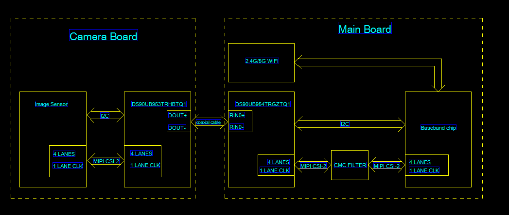
One of our customer's projects using DS90UB954-Q1 for camera, but now we encounter a problem that the reception sensitivity of WIFI was impacted when the camera is turned on. 

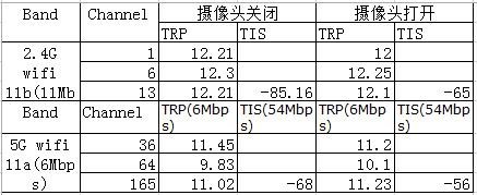
The reception sensitivity of Wi-Fi 2.4G and 5G deteriorated significantly when the camera function was turned on.The data are as follows:


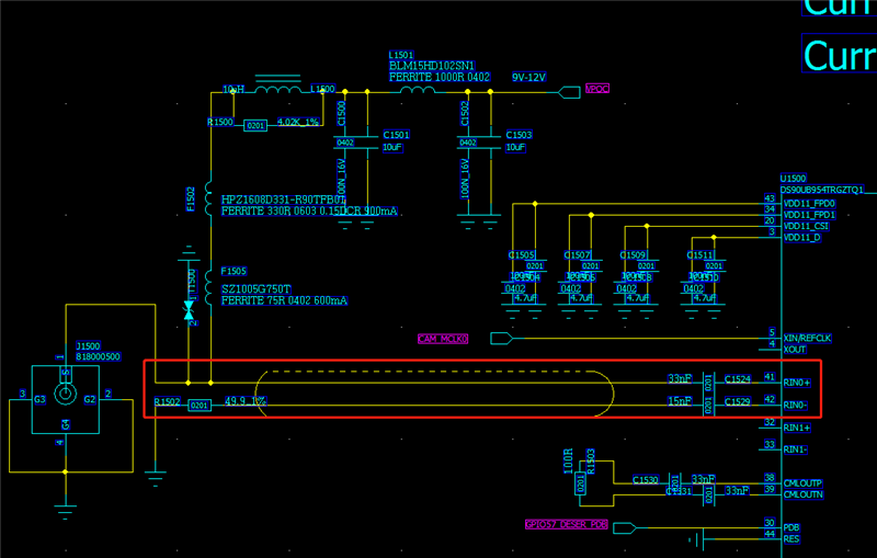
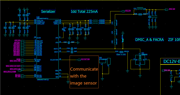
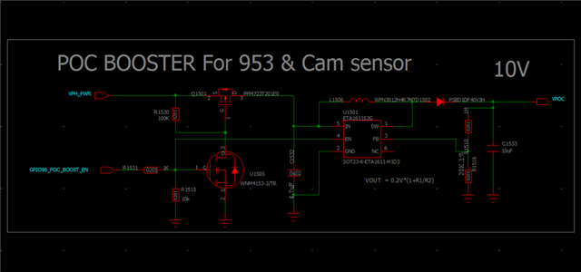
The camera and WIFI module are powered independently. The boost circuit of DS90UB953-Q1 is as follows,

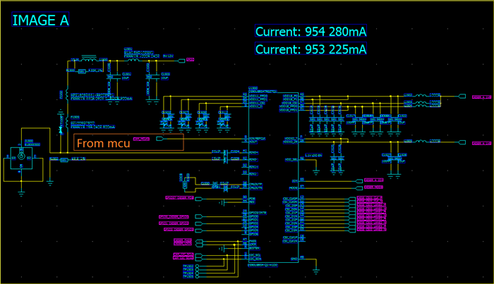
Part of the design circuit of DS90UB954-Q1 is as follows,

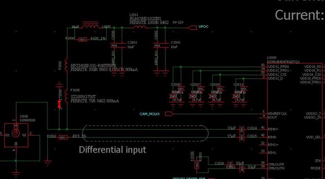
We suspect that this problem is caused by MIPI interference during signal transmission, so we consider adding filters on the line RIN0 to reduce noise interference. Whether the idea is feasible? Or can u give us some better suggestion?

Thanks,

Best Regards

  • Hello Lumina,

    1) I am not sure how you are operating the SER-DES pair, in which Mode/Clock! Nevertheless, the max. link frequency our devices are using is ~2.1GHz which is below than your WiFi frequency. Of course this can be any harmonics but to be able to know that, I need to know your clocking mode and if you are using 4G or 2G.

    2) I am not sure if I understood your topology! Can you skitch a block diagram? Where is the WiFi used?

    3) You said, you think the problem is coming from the MIPI interface, but which interface do you mean? SER input or DES output?

    4) If you are using Differential Input at the 954, then yes, you can use a CMC their which we recommend also in case of EMC issues.

  • Hello Hamzeh,Thanks for your reply!

    1,Mode=4(CSI-2 Synchronous Back Channel),CLK=24MHz

    We using single-ended 50-Ω coaxial cable for SER/DES communicate

    As shown in figure 45 .


    2,Block diagram

    3,We think the problem is coming from the “RIN0+,RIN0-“

  • Hello Lumina,

    Aside from optimization of the system shielding and ensuring cable with good shielding effectiveness specs is used, a couple of other options we would suggest for reducing radiated EMI from the 953/954 link are:

    - Use a REFCLK on the 954 with spread spectrum (this will spread the back channel reference to the 953 and then since 953 uses the back channel to generate the forward channel, it would also spread the forward channel to reduce peak energy

    - Try using non-synchronous AON clock mode with the 953 instead of synchronous mode (strap 953 for AON clock mode and set the 954 back channel to 10Mbps instead of 50Mbps) 

    Best Regards,

    Casey 

  • Hello Casey ,Thanks for your reply!

    1,Use a REFCLK on the 954 with spread spectrum (this will spread the back channel reference to the 953 and then since 953 uses the back channel to generate the forward channel, it would also spread the forward channel to reduce peak energy

    2,Try using non-synchronous AON clock mode with the 953 instead of synchronous mode (strap 953 for AON clock mode and set the 954 back channel to 10Mbps instead of 50Mbps) 

    How should we modify the above points in the program,our software engineer have checked code and document,cannot know how to modify it,Could you give us the more guide,looking forward your reply,Thanks!

  • Hello Jimmy,

    1,Use a REFCLK on the 954 with spread spectrum (this will spread the back channel reference to the 953 and then since 953 uses the back channel to generate the forward channel, it would also spread the forward channel to reduce peak energy

    For this option you just need to strap the parts to work in synchronous mode and then make the HW change. There is no SW needed 

    2,Try using non-synchronous AON clock mode with the 953 instead of synchronous mode (strap 953 for AON clock mode and set the 954 back channel to 10Mbps instead of 50Mbps) 

    Strap the 953 to non-synchronous AON clock mode with the MODE pin or use 953 register 0x03 to set the mode. On the 954 use register 0x58 to change the BC speed to 10Mbps 

    Best Regards,

    Casey 

  • Hello Casey,

    We have researched the 954 and 953 document
    We have tried to modify the code.
    Please see the attachment in the "sensor.c" and "sensor_init.c"
    The sensor_init.c is the code without modification.
    But we found that the register of the 953 cannot set success.
    The serial log see the attachment of "serial.log".
    [   23.378063] DS90UB954_Q1_powerup: DS90UB954_Q1_powerup 954 write 0x58 value=5a
    [   23.398490] DS90UB954_Q1_powerup: DS90UB954_Q1_powerup 954 read 0x58 value=5a
    [   23.478169] DS90UB954_Q1_powerup: DS90UB954_Q1_powerup 953 write 0x03 value=4b
    [   23.484785] DS90UB954_Q1_powerup: DS90UB954_Q1_powerup 953 read 0x03 value=48

    Please help us check this problem,Thank you!
  • Hello Jimmy,

    You need to set bit 4 in the 0x03 register to enable the MODE override so it would be 

    DS90UB954_Q1_powerup: DS90UB954_Q1_powerup 953 write 0x03 value=5b

    Best Regards,

    Casey 

  • Hello Casey,

    We have modify the code according to your advice.
    But we have found the camera cannot preview.
    The attchment is the error log and the good log(no-modify).

    Please help us check this problem,Thank you!

    We made the following changes to the hardware

    1,We made the following modifications for Mode Pin of DS90UB953-Q1 

    2,We made the following modifications for Mode Pin of DS90UB954-Q1

     4604.log.rar


  • Hello Jimmy,

    There is no attachment in your post 

    Best Regards,

    Casey 

  • Hello Casey,

    I'm sorry for the modification just now. Please check it again. It should be available now  

  • Hello Jimmy,

    Please reverse the order of changing the 953 MODE and changing the BC speed on the 954 like this:

    - Power up the system; 953 and 954 initially link in synchronous mode with 50Mbps BC

    - Program 954 register 0x58 = 0x7E to enable auto ACK with 50Mbps back channel

    - Program 953 register 0x03 = 0x5B to switch to AON clock mode

    - Program 954 register 0x58 = 0x5A to switch to 10Mbps back channel 

    Now you should re-establish lock with AON clock mode and 10Mbps back channel. Confirm that it worked by reading the lock status in 954 and by reading any register from 953 

    Best Regards,

    Casey 

  • Hello Casey

    We have researched the code and fond the init of 954 and 953 have two modules
    According to the explanation of the other colleague, Because 954 and 953 need I2C communication in the early power-up, so the init code alao be added to the file of msm_eeprom.c.
    But because of consumption,the project need close the 954 and 953,so when the system close camera app,the code need be added in the file of msm_sensor.c.
    According to your new advice,we have modified the code.
    So about this problem,our modification have been added in the two files.
    But the problem is existed.
    Please see the attachment of "wifi_problem_20211122.rar".
    The 'init_msm_eeprom.c' and 'init_msm_sensor.c' are the file with initial code.
    The '20211122_msm_eeprom.c' and '20211122_msm_sensor.c' are the file with modification.
    We have provided the serial.log.('serial_good.log' is normal log no-modification.'serial.log' is the current log with problem.
    Please help us analyse it!
    Thanks a lot!

    wifi_problem_20211122.rar

  • Hello Jimmy,

    So what you are seeing is that after 954 BC speed is configured to 10Mbps you can no longer communicate with the 953 or the sensor? But prior to that it looks like you can read back that 0x03 = 0x5B on the SER side which is curious. Can you try adding a digital reset to the sequence of 953 as well like this?

    - Power up the system; 953 and 954 initially link in synchronous mode with 50Mbps BC

    - Program 954 register 0x58 = 0x7E to enable auto ACK with 50Mbps back channel

    - Program 953 register 0x03 = 0x5B to switch to AON clock mode

    - Program 953 register 0x01 = 0x01 to perform a digital reset 

    - Program 954 register 0x58 = 0x5A to switch to 10Mbps back channel 

    Best Regards,

    Casey 

  • Hello Casey

    According to your advice,we have modified the code,But the problem is existed.
    The file with modification is in the attachment “wifi_problem_20211123.rar”.
    Other,the serial log have some key information:
    [ 9.594247] DS90UB954_Q1_init: DS90UB954_Q1_powerup 953 read 0x01 value=0
    The 0x01 register cannot be set 0x01 value.
    Please help us check it!
    Thanks a lot!

    wifi_problem_20211123.rar

  • Hello Jimmy,

    0x01 is a self clearing register on 953 so if you set it to 0x01, then read it back you will get 0x00. 

    After this process do you see LOCK status in 954 register 0x4D?

    Best Regards,

    Casey 

  • Hello Casey

    According to your advice,we have added the information of the 0x4d register.
    The file with modification is in the attachment “wifi_problem_20211124.rar”.
    The serial log is "dm1124.log".
    Please help us check it!
    Thanks a lot!

    wifi_problem_20211124.rar

  • Hello Jimmy,

    The logs indicate that after the switchover the 954 and 953 are locked so not exactly sure what the issue is here. Is the sensor itself not responding to I2C commands? Can you send the schematic for the sensor board? One difference I can think is that in AON clock mode the 953 does not output a CLKOUT to the sensor link it does in synchronous mode. Maybe the sensor is expecting an output clock from the 953?

    Best Regards,

    Casey 

  • Hello Casey

    The following is the schematic diagram of the 954 and 953 sensors,Thank you!

    1,DS90UB953TRHBTQ1

    2,DS90UB954TRGZTQ1

  • Hello Jimmy,

    It looks like this sensor does have a connection for CLKOUT. In AON clock mode there is no CLKOUT to the sensor - can you confirm if this would cause a problem in your system?

    Best Regards,

    Casey

  • Hello Casey,
    Your advice is checking software code?
    We're not familiar with that
    Can you give us some solution?
    Thanks!
  • Hello Jimmy,

    What I'm saying is not related to SW code. On the HW level if the sensor needs a CLKOUT from 953 to operate then this solution to use AON clock mode will not work since CLKOUT is not available from the 953 in AON clock mode. In that case a better option would be to use synchronous mode with a spread spectrum clock on the deserializer REFCLK 

    Best Regards,

    Casey 

  • Hello Casey,

             You mean is on the HW level 953 need Set to the non-synchronous mode,954 need Set to the synchronization mode ?

                                                                                                                                                                                          Thanks!

  • Hello Jimmy,

    No, I mean at the HW level it looks like your sensor is expecting a CLKOUT from 953 which is only available in synchronous mode. In asynchronous mode the CLKOUT is not available. If the sensor needs a clock, then an alternative would be to provide an external oscillator to the sensor instead of feeding it from 953. If the sensor HW can not be changed, then the only option I can suggest would be to use an SSC REFCLK on the deserializer side 

    Best Regards,

    Casey