This thread has been locked.

If you have a related question, please click the "Ask a related question" button in the top right corner. The newly created question will be automatically linked to this question.

TUSB1002A: is there any default setting to operate TUSB1002A?

Part Number: TUSB1002A
Other Parts Discussed in Thread: TUSB1002, TUSB1044

Hello TI experts,

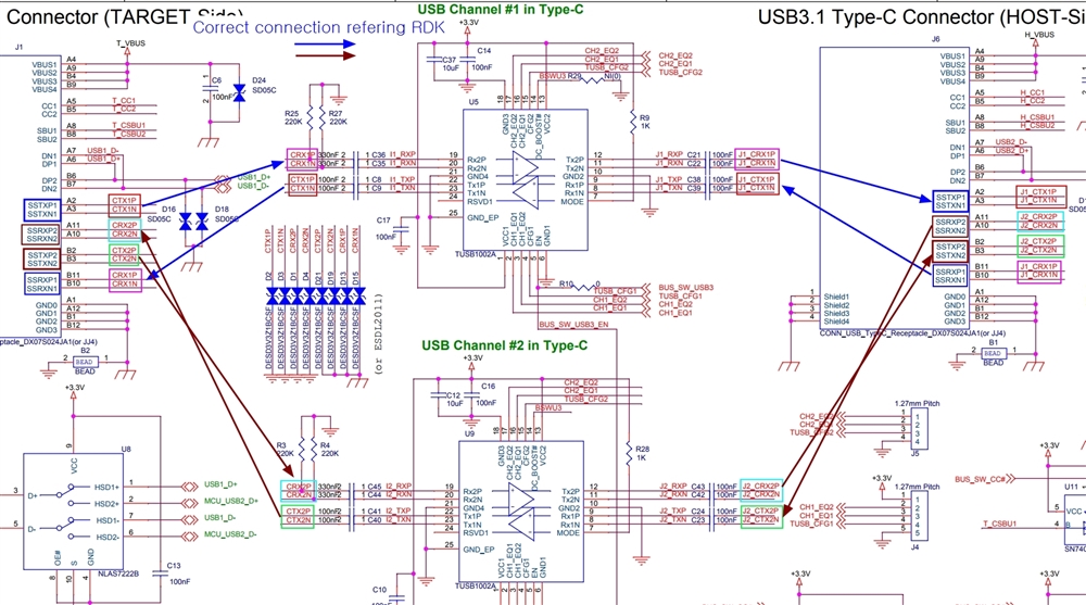
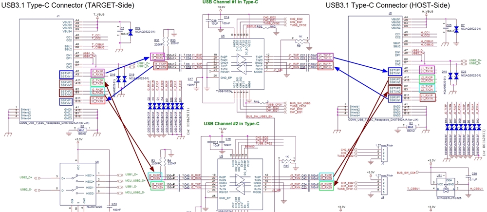
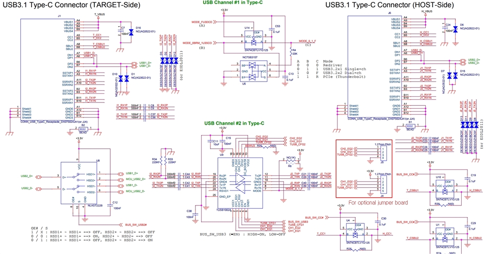
My customer considered TUSB1002A for their new product, and i reviewed a schematic few months ago below;

https://e2e.ti.com/support/interface-group/interface/f/interface-forum/1001620/tusb1002-please-review-the-schematic

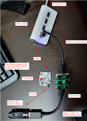
and they made their own PCB, but it does not work at all.

I think there are some default settings that made by the jumpers shown in TUSB1002A EVM (JMP1~8 and J1~3).

could you guide me about these default settings that TUSB1002A works at first time?

and if there are any other settings (power settings, cable length, etc..) please let me know.

Please check this issue. Thanks.

Best regards,

Chase

  • Hi Chase,

    Can you share more details when you say PCB does not work at all? Does a USB 3 device enumerate as USB 2? Or is there no connection at all. Can you share the most recent schematic? Customer should confirm VCC and EN (both around ~3.3V) are at the appropriate levels. Is this a USB application? If so, is MODE pin floating?

  • Hi Malik,

    Thank you for your support.

    I thought I replied 2 days ago, but something was missed. anyway I will answer your question first.

    1. VCC and EN is 3.3V.

    2. it is a USB application, for the bridge between computer and USB memory drive.

    3. MODE pin is both available to set GND and 3.3V. please see the schematic below. if there are any proper setting please let me know.

    Actually my customer got TUSB1002A EVM this morning, and they found some difference between their own schematic and EVM schematic.

    here is the old schematic, you can also see it in the link above.

    and the schematic below is modified, based on the TUSB1002 EVM.

    You can see that RX1x, TX1x, RX2x and TX2x net pair is different, compared to former and new version of schematic. (i am sorry that the arrow line of former schematic is wrong)

    anyway I and my customer think that TUSB1002A has dedicated input and output port, so we were complicated about this and drew wrong direction for the signal. could you confirm it first?

    also I attach a picture of the test environment. please tell me if you find anything wrong, including cable length or anything.

    (jumper board is for setting EQ and CFG pins. first we tried to find proper settings for the IC, using different jumper settings.)

    and final question, do you have any reference schematic for type C usb connector and TUSB1002A? (there is attached USB 3 A type connector) it would be very helpful for me and my customer.

    Please check these issues. Thanks.

    Best regards,

    Chase

  • Hi Chase,

    One question before I review: is there a specific reason to go with 2 TUSB1002A instead of TUSB1044? TUSB1044 is design specifically for this kind of application with USB-C connectors. Is this meant to be a USB3.2 x2 application? 

  • Hi Malik,

    Thank you for your support.

    Actually now I realized that TUSB1044 is more suitable for customer's application.

    no, there is just 1 usb type c application. there are 2 upstream&downstream in one connector, so the customer designed 2 TUSB1002A like this schematic.

    anyway please confirm the direction of the signal line first.

    Best regards,

    Chase

  • Hi Chase,

    I do not think you need to swap on the target side. USB-C receptacle TX should be connected to TX. Is this intended to be a final product or a test board? USB-C receptacle to USB-C receptacle dongles like this are technically not allowed. 

    The USB-C connector TX and RX lanes should not operate as separate ports. One USB-C receptacle should  operate as one upstream port or one downstream port. 

  • Hi Malik,

    Thank you for your support.

    I do not think you need to swap on the target side. USB-C receptacle TX should be connected to TX.
    -> Then, Should I swap host side as new schematic, and keep target side as old schematic?

    Is this intended to be a final product or a test board?
    -> It is almost final product. I will ask it to my customer.

    USB-C receptacle to USB-C receptacle dongles like this are technically not allowed.
    -> what is the reaon for not allowed? i think receptacle and plug have same pin maps, so I can use any type of it.
    -> Can I use like this although it is "technically" not allowed?
    -> how about TUSB1044? is it allowed for this kind of situation?

    The USB-C connector TX and RX lanes should not operate as separate ports. One USB-C receptacle should operate as one upstream port or one downstream port.
    -> it sounds like I cannot use 2 ICs for one type-c application. is it right? cause another expert said nothing about it when I requested review of my first schematic.

    and here is another question.

    - what is the difference between single channel operation and dual channel operation about MODE pin?

    - is it possible to short TXP1 and TXP2 / TXN1 and TXN2 and so on? then I think we can use one IC for this application.

    Please check these issues. Thanks.

    Best regards,
    Chase

  • forgot the redriver in between , as Malik mentioned USB-C receptacle to USB-C receptacle dongles like this are technically not allowed. 

  • Hi Brian, Malik,

    Thank you for your support.

    Could you check the other questions?

    Best regards,

    Chase

  • Hi Brian, Malik,

    Today I got modified schematic from my customer. please see the schematic below ;

    Major difference is that there are only 1 TUSB1002A, instead of 2.

    and they tied RX1P and RX2P / RX1N and RX2N / TX1P and TX2P / TX1N and TX2N, to use only 1 TUSB1002A.

    Please confirm that it is okay to use TUSB1002A like this.

    and here are some more questions.

    - How can I determine the value of capacitors which are connected in the line in series? (C8, C9, C37, C36, and so on)

    - Is it okay to change the size of these capacitor? If I change the size to bigger or smaller (from metric 1005 to 1608 or 0603) should I also change artwork of the PCB?

    - and please check the questions that I posted 3 days ago.

    The customer is in end of their design. Your support would be very helpful for my customer.

    Best regards,

    Chase

  • Hi Chase,

    Sorry I was out Friday, let me clarify some things.

    USB-C receptacle to USB-C receptacle dongles like this are technically not allowed.
    -> what is the reaon for not allowed? i think receptacle and plug have same pin maps, so I can use any type of it.
    -> Can I use like this although it is "technically" not allowed?
    -> how about TUSB1044? is it allowed for this kind of situation?

    First the USB-C spec does not allow for devices with USB-C receptacles on both sides. In this design your customer will need to change one connector to a USB-C cable (creating a direct attach device) or include captive cable. The reason for this is due to cable orientation mismatch between the two receptacles. Even though pin mapping is the same. TUSB1044 would fit better but plug should still be used one side. Technically you can build this board but it may not pass USB -C compliance testing and will most likely have interop issues. Customer should refer to TUSB1044EVM which would fit this application very well. 

    is it possible to short TXP1 and TXP2 / TXN1 and TXN2 and so on? then I think we can use one IC for this application.

    Second, A single USB-C connector should not connect two different USB host or endpoints. There should only be a one to one correspondence. x2 operation does not and a second lane for use by a different endpoint, this lane is only added to help increase data throughput. 

    I do not recommend using the latest shcematic. You should not tie TX1/2 and RX 1/2 net together. The issue here is not with TUSB1002A, this product would most likely have interoperability issue with other USB-C devices on the market. 

    Is this a USB only design, no DP alternate mode or other alternate modes? 

    - How can I determine the value of capacitors which are connected in the line in series? (C8, C9, C37, C36, and so on)

    TX1/2 should be AC coupled with 220nF and RX1/2 should be AC coupled with 330 nF. This is highly recommended when AC coupling to a USB-C connector. Again TX1/2 and RX1/2 should not be tied together at the USB-C connector. 

    - Is it okay to change the size of these capacitor? If I change the size to bigger or smaller (from metric 1005 to 1608 or 0603) should I also change artwork of the PCB?

    Customer should only use 0201 AC coupling caps for the best result. I do not recommend using AC coupling caps bigger than 0204 if needed. 

    - what is the difference between single channel operation and dual channel operation about MODE pin?

    In Single Channel mode TUSB1002A will disable one lane based on receiver detect function. For you design you should use dual lane mode to keep both lanes active. 

    I do not think you need to swap on the target side. USB-C receptacle TX should be connected to TX.
    -> Then, Should I swap host side as new schematic, and keep target side as old schematic?

    You should keep the target side the same as the old schematic. Host side in new schematic should stay as is. USB-C receptacle TX should be connected to TX pins and USB-C receptacle RX should be connected to RX pins.