This thread has been locked.

If you have a related question, please click the "Ask a related question" button in the top right corner. The newly created question will be automatically linked to this question.

DS90UB941AS-Q1: Please recommend a deserializer part number output for 1080P display using

Part Number: DS90UB941AS-Q1
Other Parts Discussed in Thread: DS90UB928Q-Q1, DS90UB948-Q1, DS90UB926Q-Q1, DS90UB940N-Q1, DS90UB924-Q1

Hello Sir:

We want to use EVM, please refer the link as below.

Jacinto7 DRA829/TDA4VM Evaluation Module (EVM) Users Guide (Rev. B)

We want to connect a display, and the max resolution should be 1080P.

Can you provide a deserializer part number output for 1080P display using?

Please let us know your recommendations.

Thanks a lot. 

  • Hello,

    The DS90UB941AS-Q1 can be used with DS90UB940N-Q1, DS90UB948-Q1, DS90UB924-Q1, DS90UB926Q-Q1 or DS90UB928Q-Q1 deserializers. Since you are using 1080p resolution, I would recommend DS90UB940N-Q1 or DS90UB948-Q1 (full video timing would be needed to determine which DES are compatible or not). What output format do you need? The 940N outputs Mipi CSI-2, and the 948 outputs OpenLDI.

    Regards,

    Ben

  • Hi Ben:

    Our requirement format has two format MIPI DSI and LVDS.

    Please refer our panel spec as attached files.

    VL156-192108YL-C02_spec.pdfG101UAN02.0_180420(final).pdf

    I'm not sure that OPEN LDI format is equal to LVDS or not, but I check 948 datasheet and our LVDS panel spec, that signals seems the same type. 

    Can you help us to double confirm does 948 output signal is suitable for our LVDS panel?

    Our other panel require MIPI DSI format, can you recommend a deserializer part number which output format is MIPI DSI?

    Please help to provide your recommendations for us.

    Thanks a lot.

  • Hi Statham,

    Yes, the 948 OpenLDI output is compatible with an LVDS display. Unfortunately, we do not currently have any deserializers that output MIPI DSI. The solution I can suggest is using one of the deserializers we have available, and converting that output signal to MIPI DSI with another device.

    Regards,

    Ben

  • Hi Ben:

    We have been finished our schematic.

    Please refer the attached file.

    Would you please help us to check it and provide recommendations for us?

    Any recommendations please let us know.

    Thanks a lot.

    941+948.pptx

  • Hi Statham,

    I will check the schematic. The turn around for schematic reviews are usually one week, so I will get back to you with my recommendations by Friday 12/3.

    Regards,

    Ben

  • Hi Ben:

    Thanks your support, looking forward your feedback.

  • HI Statham, 

    See my feedback below:

    941AS

    • IDX - For 7-bit address 0x0C, pullup should be open.

    • MODE_SEL0 - for mode no. 7, pulldown should be open

    948

    • IDX - For 7-bit address 0x2C, pullup should be open.

    • MODE_SEL0 - R32 and R35 should NOT be populated at the same time or if using SW1. For mode NO. 0 (Dual OLDI output), pullup should be OPEN)

    • MODE_SEL1 - R36 and R39 should NOT be populated at the same time or if using SW2.
    • GPIO2/GPIO3 - unused GPIO pins should be tide to external pulldown
    • LOCK - Why is LOCK pulled up to VDDIO?
    • VDDIO - ferrite bead should be DCR <= 0.3Ohm; Z = 1kOhm@100MHz. Recommend MPZ1608S102A
    • VDD33_x - ferrite bead should be DCR <= 0.3Ohm; Z = 1kOhm@100MHz. Recommend MPZ1608S102A

    Let me know if you have any other questions or concerns.

    Regards,

    Ben

  • Hi Ben:

    Thanks a lot your great support, we still have a few questions as below.

    If we want to have remote function, it be likes below behaviors, please let us know is it possible to be or not.

    1. Can we make a mirror function on 941 and 948 D_GPIO? Such as, SOC configure 941 D_GPIO1 high level, then 948 mirror D_GPIO1 get high level too.

    2. If an INT signal from touch panel and pass trough 948_INTB_IN, does 941_REM_INTB will send INT signal to SOC_INT?

    Please help to provide your recommendations for us.

    Thanks a lot.

  • Hi Statham,

    1. Yes, you can configure the 941AS D_GPIO1 to receive input (in this case from SOC), then configure the 948 D_GPIO1 for Remote GPIO Control. In this configuration, the 948 GPIO pin will be an output, and the value is received from the remote Serializer. See the respective datasheets for descriptions of the necessary registers.
    2. The 941AS can receive an INT signal from the 948. Configuring the SOC to receive the INT signal from the 941AS would be dependent on your design.

    Regards,

    Ben

  • Hi Ben:

    We have been updated our schematic, would you please help to check it again?

    I send the files by messages.

    The other we have two application questions

    1. our panel spec shows below and will provide full datasheet by messages

    a. 1920x1080,D0-D7 (VL156-192108YL-C02_spec.pdf

    b. 1280x800, D0-D3 (VL101-12880YL-C13_spec.pdf)

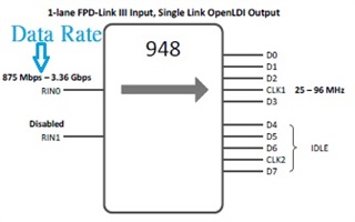
    948 supports 1 or 2 lane FPD-LINK III input and dual link OpenLDI output, if we only use one lane RIN0+/-, does 948 can output dual link OpenLDI in the same time? 

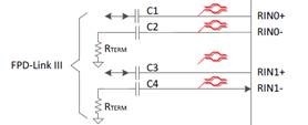
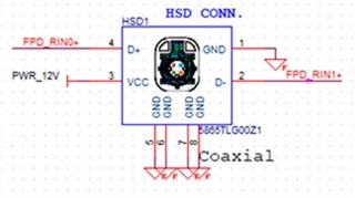
    2. If 941+948 supports 2 lane FPD-LINK III input, did you recommend use the same coaxial? and can we use the same HSD connector?

    Please refer the figures as below.


    3. base on our design, did you have a guide line to teach us how to calculate the HSD data rate??

    Any recommendations please let me know.

    Thanks a lot.

  • Hi Statham,

    I will take a look again at your schematic, and get back to you mid-late next week.

    As for your other questions:

    1. Regarding the two panel specs you sent me, I could only find LCD timing for 1280x800 and 960x1080, not 1920x1080. As for the configuration of the 948, the device can be configured in following modes:
      • 1-lane FPD-Link III input, single-link OpenLDI output
      • 1-lane FPD-Link III Input, Dual Link OpenLDI output
      • 2-lane FPD-Link III Input, dual-link OpenLDI output
      • 2-lane FPD-Link III Input, single-link OpenLDI output
      • 2-lane FPD-Link III Input, single-link OpenLDI output (replicate)
    2. Yes, you can use the same cable/connector. See our EVM for an example.
    3. The FPD line rate is PCLK*35

    Let me know if you have any additional questions.

    Regards,

    Ben

  • Hi Ben:

    About the LCD timing is in page 9 of datasheet, 1920x1080.

    The other LCD timing is in page 10 of datasheet, 1280x800.

    Please refer below figures.

    Thanks.

  • Hi Statham,

    Ah I see, I misinterpreted the 1920x1080 timing table. Thank you. I'll get back to you with my schematic feedback later this week.

    Regards,

    Ben

  • Hi Statham,

    Thank you for being patient. Most of the issues I saw before have been improved. See my feedback below:

    941

    • IDX - For 7-bit address 0x0C, pullup should be open. *attach table*
    • MODE_SEL0 - SW1(2) (splitter mode #7) pulldown should be open. See table. R51 and R54 should NOT be populated at the same time or if using SW1.
    • PDB - PDB circuit not shown
    • INTB - see previous INTB comments

    948

    • IDX - For 7-bit address 0x2C, pullup should be open.
    • MODE_SEL0 - R32 and R35 should NOT be populated at the same time or if using SW1. For mode NO. 1 (Dual OLDI output), pullup should be OPEN)
    • MODE_SEL1 - R36 and R39 should NOT be populated at the same time or if using SW2.

    Regards,

    Ben