This thread has been locked.

If you have a related question, please click the "Ask a related question" button in the top right corner. The newly created question will be automatically linked to this question.

SN65DPHY440SS: Question about SN65DPHY440SSRHRR

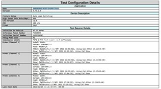
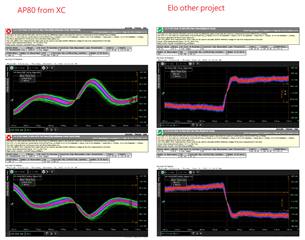
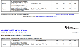
Part Number: SN65DPHY440SS

Hello:

My client found that the analysis of d0231 auxiliary screen ESD problem is related to Mipi retimer ic-sn65dphy440ss and needs TI support,

At this stage, the hard control scheme is adopted, later the soft control scheme needs to be verified, and My client wants TI to release the reference code, Thanks!!!

  • Hi,

    The DPHY440 will work in pin-strap mode and will also work in I2C mode with default I2C registers value.

    Thanks

    David 

  • Hi David:

    The software mode means it does not require CPU configuration and can be used when connected to I2C,Is that right?

  • Hi,

    You can configure the DPHY440 with external pullup/pulldown resistors, there is no need for the GPU to configure the DPHY440.

    Thanks

    David 

  • Hi David

    My client actually configure the DPHY440 with external pullup/pulldown resistors,But ESD problem existed. Could you give some suggestion to check this

  • Hi,

    I don't understand how pullup/pulldown configuration of the DPHY440 can be related to the ESD problem, can you please elaborate? Do they have any ESD protection in their design?

    Thanks

    David

  • Hi David

    After using sn65dphy440ss, the screen will be black when ESD air is 6kV. After removing sn65dphy440ss, ESD air 8Kv is OK

    The customer has taken grounding measures, but the effect is not great

  • Hi,

    Have they add any ESD protection on the DPHY440 output?

    Thanks

    David

  • Hi David:

    1. Environmental physical grounding measures are introduced into ESD test fail;

    2. Power pin and register configuration pin are added to ESD device test fail;

    3. Modify the external resistance configuration register to enhance TX, and add the above measures to test fail;

    4. Mipi plus ESD device has not been tested yet, but it is generally not recommended to add it. The capacity value of TVs will affect HS signal and eye diagram.

    Just now, My client said the I2C default configuration (plus physical grounding + TVS) verification fails. Please support the analysis.

  • Hi,

    ESD protection is a system level design and not just limited to DPHY440. How are they connected their board to the environmental physical grounding? Can they share their schematic and layout?

    Thanks

    David

  • Hi,

    The DPHY440 looks to be an embedded design, do they have the entire test until closed when they are doing the air ESD test? 

    And where do they apply the air ESD test?

    Thanks

    David

  • Hi David:

    My client think it is not caused by the test environment. In the same environment, when skipping Mipi sndphy440 , the ESD test is OK. So Please help check other factors  which will cause this problem.

    Now My client's project tests ESD fail (contact and air), and the verification results show that it is related to sn65dphy440;

    ESD devices and physical grounding measures are added to the periphery, and the verification is still fail, but the Verification ESD pass when this IC is removed;

  • Hi,

    ESD devices and physical grounding measures are added to the periphery, can they share what they have done? My expectation is that with proper ESD protection in place, the ESD will get discharged to the earth ground and then will not impact the DPHY440 operation.

    Thanks

    David

  • Hi David:

    The previous schematic PCB and grounding measures have been sent to you before. Please check it. Thank you!

    4621.D0231 ESD装机措施_20211026.doc

    6558.D0231_SUB_LCD_PCB_V1_0A_20210726-1940-ref-s.pcb

    3527.D0231_SUB_LCD_SCH_V1.0A_20210727_1058.sch

    Now the verification results are as follows:

    1. Environmental physical grounding measures are introduced into ESD test fail;

    2. Power pin and register configuration pin are added to ESD device test fail;

    3. Modify the external resistance configuration register to enhance TX, and add the above measures to test, fail;

    4. Mipi plus ESD device has not been tested yet, and removing sn65dphy IC, Verification pass

    5. According to your FAE reply, use I2C default register to verify fail;

    6. After trying to use the external capacitor to reset, the drawing will not be displayed, and  using the original external GPIO port control to reset can be displayed;

    Please help to analyze and reply to the above information, thank you!

  • Hi,

    The DPHY440 is not an ESD protection issue, so it looks like there is ESD energy that is not being dissipated through the environmental physical grounding measure gets coupled into DPHY440 and cause the screen to go black. I do not expect putting the DPHY440 into pin-strap or I2C mode would fix this issue.

    They have to improve their environmental physical grounding measure or use external ESD protection device in order to pass the ESD test, but this is outside of the DPHY440 design.

    Thanks

    David 

  • Hi David:

    Now use I2C to read the sn65dphy440 IC register value. The changes before and after ESD are as follows:

    It is found that the value of 0x0D register has changed and other register values remain unchanged. Would you please help analyze,Thanks!!!

  • Hi,

    Register 0x0D reports contention being detected on lane 0 interface. Again, they need to improve their system ESD design to ensure the DPHY440 can work correctly.

    Thanks

    David 

  • Hi David:

    The electrostatic problem has been improved. Now there are 6 fail items in the Mipi eye diagram tested after sn65dphy. Please help analyze and support,

    Attached is the eye chart test report, please check it.

    D0231-MIPI 眼图(retimer IC).pdf

  • Hi,

    Part of the failure is to verify that the AC Common-Mode Signal Level Variations between 50 and 450 MHz (VCMTX(LF)) of the DUT Data Lane HS transmitter are below the maximum allowable limit. But there is no control in the DPHY440 that actually controls the AC common mode signal level. Can you verify they have sufficient solder coverage for the thermal pad?

    Thanks

    David

  • Hello David:

    1、The thermal pad of sn65dphy eats tin well and enters the main place, as shown in the figure below;

    2. As for the mechanism that retimer IC does not control AC common mode level, how to increase the mechanism, and whether it can be changed by modifying the default register value of retimer,

    Now the default value of the register is shown in the figure below. Please help analyze and give appropriate methods or modification suggestions;

    3、Can you make a simulation to see the simulation situation according to the schematic diagram and PCB layout provided last time?

  • Hi,

    Register 0x0E bit [5:4] controls the HS TX voltage TX SWING level

    00 – 180mV
    01 – 200mV 
    1X – 220mV 

    Bit[1:0] controls the HS TX Pre-emphasis

    00 – 1.5dB
    01 – 0dB 
    1X – 2.5dB 

    The failed test is AC Common-Mode Signal Level Variations between 50 and 450 MHz which can't be controlled by the DPHY440. 

    Thanks

    David

  • Hello David:

    Does TI have demo board EA report of DPHY440? Could DPHY440 itself meet spec for sure?
    What’s possible Influencing factors to cause fail of (VCMTX(LF)), like power /ground noise of DPHY440?
    My customer checks the design with EMC common mode chock for each pairs, any characteristic need attention for common mode chock?

  • Hi,

    We have not done the MIPI compliance testing of the DPHY440, so we do not have a compliance report for it.

    But are they seeing any functional issue with the current implementation?

    Thanks

    David

  • Hello David:

    Do you mean that the rate of front-end Mipi CLK should reach 450M at least? Can it not be controlled by snd65phy below 450M?

  • Hi,

    The DPHY can support minimum of 100MHz and maximum of 750MHz. 

    My question is

    1. Are they seeing functional failure or just compliance failure?

    2. For the compliance failure, the failed test is AC common mode voltage which DPHY440 does not control.

    Thanks
    David 

  • Hello David:

    From the current phenomenon, the function is OK, and the image can be displayed normally without abnormality;

    For the second point of compliance failure, how to rectify or what is the direction of rectification? Could you give me some advice?

    In addition, please ask if you can communicate via email. Thank you!!!

  • Hi,

    I accept your friendship request, we can communicate using the private message.

    What equipment did they use for testing? Do they have the termination board setup for the MIPI compliance testing?

    Thanks

    David

  • Hello David:

    Our test equipment is " Keysight MSOS804A Mixed signal Oscilloscope"(8 GHZ  20GSa/s 10-bit ADC

    Conformance test app: D9020DPHC MIPI D-PHY Testversion3.73.1.0

    CTS version:V1.0

  • Hi, 

    Do they also have the active termination board connected as shown below?

    Thanks

    David

  • hello David:

    My client didn't sample test board. We tested it from flying wire (short enamelled wire) at test point

    Other projects of my client are also tested in this way.

  • Hello David:

    Brief description of the project: double screen display of desktop cash register, The CPU is MediaTek mt8365 (i350). Because the main screen occupies the platform Mipi interface, the implementation scheme of auxiliary screen display is CPU DPI (RGB 8bit dual edge) to DSI Mipi (the conversion IC uses Longtium lt9211_u5, which is placed on the main board side). However, due to the limitation of structure ID, the main board is far from the auxiliary screen interface (about 300mm), so ti sn65dphy440ss is added to the sub screen panel to enhance RX EQ, adjust the risk and fall timing of HS data / CLK, so as to adjust the Mipi effect and enhance the transmission distance.

    Remarks: 1 The cable adopts twisted pair (170mm), and both FPC and PCB have 100 Ω± 10% impedance matching:

    2. Since the ESD problem was solved before, I2C mode is adopted now.

    Problems encountered: test signal integrity Mipi eyes fail. Please help explain and give modification suggestions for the frequently reported fail items in the following reports. The corresponding test reports and specifications will be uploaded in the annex. Please check.

    Our test instruments use keysight msos804a mixed signal oscilloscope "(8 GHz 20gsa / s 10 bit ADC), d9020dphc Mipi d-phy test (version: 3.73.1.0), CTS version: v1.0, continue CLK

    1)1.3. 11{HS Data TX 20%-80% Rise Time (tR)} ,1.3. 12 {HS data TX 80% - 20% fall time (TF)} reports error fail. Can I modify the 0x0b register of ti-sn65dpy to improve it? Please refer to the test report to give the register modification value.

    2)1.4. 9 {HS Clock TX Common-Level Variations Between 50-450MHz(VCMTX(LF))},1.4. 4 {HS Clock TX Differential Voltage(VOD0 Pulse)},1.4. 4{HS Clock TX Differential Voltage(VOD1Pulse)},1.4. 5 {HS clock TX differential voltage mismatch (pulse)} reports error fail. Can these four items be improved by modifying the 0x0e register of ti-sn65dphy? Please refer to the test report and give the register modification value.

    3)1.4. 11{HS Clock TX 20%-80% Rise Time (tR)},1.4. 12 {HS clock TX 80% - 20% fall time (TF)} reports error fail. Can I modify the 0x0a register of ti-sn65dpy to improve it? Please refer to the test report and give the register modification value.

    4)1.5. 4 {data to clock skew (tskew (TX)) (max, min), 1.5.4 {data to clock skew (tskew (TX)) (mean)}. What do these two reflect? If there is any improvement after adjusting the rate of HS data / CLK, please refer to the test report and give modification suggestions.

    Please focus on the above problems and give timely feedback. Thank you!

    5633.LT9211_Datasheet_R2.5.pdf

    MIPI D-PHY Device 1_Report_2021-12-16_1126软件修改花屏+线束包铜箔.pdf

  • Hi,

    When you are doing the test and switch from unterminated LP state to terminated HS state, you need to make sure you set the termination correctly. The question in my previous response is that do you have the active termination board set correctly when running the compliance testing? You can reference to this link for the termination board, https://www.iol.unh.edu/solutions/test-tools/mipi.

    Thanks

    David 

  • Hi David:

    My client follows the connection instructions on the mipi protocol of the oscilloscope to connect the probe and the signal。
    channel 1: TDP0
    channel 3: TDN0
    channel 2
    CLKP
    channel 4
    CLKN
    Regarding the mipi DPHY test fixture you mentioned, we don
    t have it. My client uses a short enameled wire to solder directly to the test point (as shown in the picture in the previous email). previous projects are also tested in this way.

    There is also an request on 12/20. I hope you can reply and give some advice. Thanks!!!

  • Hi,

    For MIPI, they need to switch between the open/100-ohm receiver termination for the LP and HS mode. How are they able to achieve this with the current measurement method? 

    For the question sent on 12/20, they need to make sure their test setup is correct, otherwise the results are not valid.

    Thanks

    David 

  • Hi David:

    The following figure shows the comparison between the measurement fail project provided by XC(using DPHY440) on the left and other EA pass projects of our company on the right. The wave pattern of XC is obviously deformed Pls check it, Thanks

  • Hi,
    Your issue is being reviewed by the appropriate engineer. Due to the US Holiday there may be a delay in response to your post. We apologize for any inconvenience.

  • Hi,

    Is the other project also using the DPHY440?

    The reason I was asking for the test setup is because the output clock amplitude does not match what is expected from the DPHY440 as shown below.

    Thanks

    David