This thread has been locked.

If you have a related question, please click the "Ask a related question" button in the top right corner. The newly created question will be automatically linked to this question.

DP83825EVM: Interface forum

Part Number: DP83825EVM

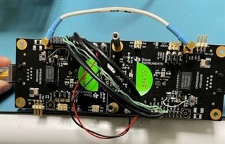
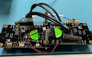
I have taken two DP83825EVM boards and connected them back-back in unmanaged repeater mode but have so far been unable to get the setup to work. 

I painstakingly reconfigured the boards to do this even though the EVM is not exactly tailored well to support all of the needed jumper/strapping options specifically for repeater mode.  Anyway, one is set up as master and the other as slave, mostly to make the clocking setup easier (feed 50MHz to slave from master and disconnecting slave's xtal).  I connected the RMII signals with very short (3") pieces of coax for the cross-connected RX & TX signals.  I have set the straps for repeater mode on both boards and slave mode (on the slave board), etc.  I have set no registers, so all of them are default except for what the hardware straps configure. 

My test setup is simple.  I connect the ethernet port from a Win 7 PC to one side of the repeater and another device (with fixed IP address) on the other side, then simply try to ping from PC to device.  The device's interface is 10/100Base-T.  Without the EVM boards in line, pinging works just fine but not with the board set in series.  This whole setup is on a single bench top (short connection lengths).  I can see each MDI side gets connected to at least some extent because when probing the TX and RX at the RJ45, I see the FLPs go away after CAT 5 is plugged in, indicating auto negotiation took place, plus activity lights stay on solid.  When I send the pings, I see the activity lights on both EVM boards flash, indicating some activity.  When I probe the RMII signals during pings from PC, I see data on the PC side (slave side) RX signals which connect to the TX pins on the device side (master) but never anything coming the other way.  If I flip the board set (PC connected to master), I see the same thing.  The 50MHz clock looks good/healthy (and is fed to from master to slave with coax).  Since repeater mode is supposed to operate unmanaged, I even disconnected the MDIO signals going to the phy from the EVM's MCU, thinking perhaps some registers were getting set on power up.  No help.  

The EVMs are brand new but I did find a thread that talked about an older version of the die have XI and XO swapped, so I even tried moving the clock input to XO on the slave, definitely no help.

I have been unable to get the USB2MDI GUI, due to a driver loading problem (I have another thread started on this problem) so I have not been able to check any register settings.

Anyone have any thoughts on this?  Are there any known bugs or hardware issues with these EVMs that has not been made public?  I have scoured the forums but found nothing.  I don't want to commit to using this chip in a design without seeing it work first.

Thanks,

Phil
  • Hi Phil,

    This configuration may not be working as the slave may not be receiving the master's clock when it needs to. Can you try resetting the slave PHY and see if that changes things? Also ensure to take care of strapping, specifically CRS_DV and RX_DV pins.

    Sincerely,

    Gerome

  • Hi Gerome,

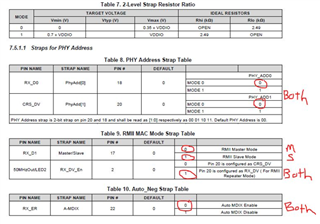
    Thanks for the response.  I have tried resetting after power up.  No help.  I feel that I set the straps appropriately for repeater mode with one master and one slave.  See below.

  • You mention "CRS_DV and RX_DV pins".  Not sure how to interpret that.  On each EVM I have pin 2 (RX_DV_EN strap) set to high, which is said to configure Pin 20 for RX_DV operation instead of CRS_DV operation.  Interestingly, the EVM has no component/pad routing to just easily utilize this particular strap option, I had to tack a resistor in place between pin 2 and VDDIO.

    I have not done anything with setting the PHY address straps at pins 18 & 20 so both have addr 00 but figured that was no problem since I am not utilizing SMI.

    Thanks,

    Phil

  • Hi Phil,

    I apologize for the confusion. I meant ensure that pin 2 strapping ensured that pin 20 (normally CRS_DV) is configured as RX_DV.

    Sincerely,

    Gerome

  • Gerome,

    Yes, I have pin 2 pulled up with a 2.49K to VDDIO to set pin 20 for RX_DV operation.  I did this on both boards.  This is the strap for which there are no pads for on the board (strangely) but I as able to "tack" a resistor in place.  I have quadruple checked everything that I can think of, based on the documentation provided. 

    This may be dumb question but since I am not using SMI for anything, and the SMI ports are isolated, is there still a need to strap/configure each board for a different PHY address on pins 18 & 20?

    Also, I purchased 4 eval boards.  When things weren't working with the first try, I configured a spare as a fresh master but still nothing.  My next try is to configure the other spare as a fresh Slave just in case that particular board is the culprit.

    All of this seems like it should be pretty straight forward, which is why I am so confused.   Any other thoughts would be helpful.  Unfortunately, I still can't get the GUI to work so I'm unable to check registers (frustrating). 

    Phil

  • HI Phil,

    PHY Address strapping is not needed if SMI is not used. The only move forward in this debug I can suggest that doesn't involve software is seeing if the boards would link up under normal circumstances (all jumpers unplugged, etc. and plugging in ethernet cable). 

    Outside of this, the next required steps would be software reading to determine if the PHY is being strapped correctly in the appropriate registers. 

    Sincerely,

    Gerome

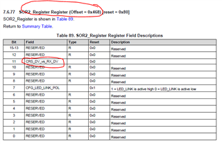
  • OK, I'm set up to read registers.  From reading registers, I have so far I been able to verify the master/slave straps are correct for each board when reading reg 0x467 and the clock setting/selection.  I'm not sure how to verify the CRS_DV / RX_DV strap, unless it is reg 0x468 bit 11.  In this case both master & slave are reporting 1290 (bit 11 = 0). Thoughts or suggested register queries?

  • Hi Phil,

    Could you please give out the full value of registers 0x467 and 0x468 please for both master and slave devices?

    Sincerely,

    Gerome

  • Hi Gerome,

    Register 0x467 is 053B (slave) and 0533 (master)

    Register 0x468 is 1290 (both)

    Thanks,

    Phil

  • Gerome,

    In case it helps, this is my connection scheme.  The light blue lines are 50 ohm coax segments (about 5" long, soldered to header w/shield grounded at both ends), the green are individual wires (5") and the Yellow is 6" coax with SMP connectors. It has occurred to me that perhaps my wires are a bit too long so my next step is to shorten them as much as possible and keep them the all as close to the same length as possible.

    DP83825i Repeater.pdf

  • Hello Phil,

    Thanks for the connection scheme. I will review.

    Sincerely,

    Gerome

  • Hi Phil,

    Looking at diagram, you did ensure to populate J14, and R46, and desolder R36, R41, correct? Just confirming to ensure you disconnect Xtal circuit on slave board and reroute to EXT_CLK so that is only source. In addition, what is CLK_OUT signal of slave board looking like?

    You also see link on both boards (Reg 0x1[2] = '1') correct?

    Sincerely,

    Gerome

  • Gerome,

    Yes, the hardware configuration for the slave clock is as you describe.  Attached is EVM change sheet that I used when I configured the boards out of the box.

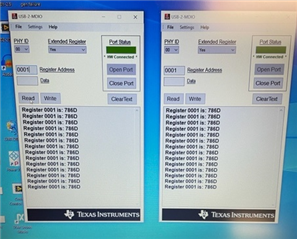
    When connected up, Reg 0x1: Slave = 786D, Master = 786D.  In image below, I have two instances of the GUI running.  One on left is master and is hooked to my device with static IP.  The one on the right is the slave which is connected to my PC.

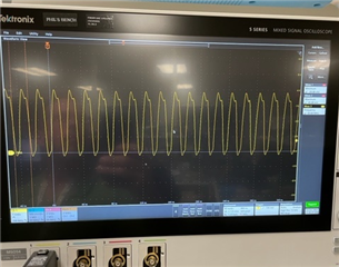
    The last image is the 50MHz clock at the Xin pin of the chip on the slave board. The CLK_OUT signal on the slave board flat-lined and pulled up to 3.3V (from repeater mode strap).

    DP83825i_EVM_straps.pdf

    Regards,

    Phil

  • Hi Phil,

    As discussed, the next point of action would be to ensure length matched and impedance matched traces are used to connect between EVMs in both slave modes with a 50MHz external clock source being provided to both boards. RMII has very tight timing requirements (see section 6.6 within datasheet) that can be impacted by long connections between boards. 

    Sincerely,

    Gerome