This thread has been locked.

If you have a related question, please click the "Ask a related question" button in the top right corner. The newly created question will be automatically linked to this question.

DP83867IS: Wrong phy address setting with strap pins

Part Number: DP83867IS

Hi all

Would you mind if we ask DP83867IS?

This thread is relation to following forum.
https://e2e.ti.com/support/interface-group/interface/f/interface-forum/1048227/dp83867is-phy-address-setting-with-strap-pins

"Please update when scope captures are available of bad reset."
"This will help determine what exactly is going one when the PHY straps into a different address during that 1 out of 400 reoccurrence. "

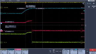
->The customer could capture bad condition and normal condition. Could you refer to the following file?

20211220_DP83867.pdf

<Question1>
There is no difference between no problem case and problem case.
-problem case : 296mV
-no problem case : 288mV
The voltage is within from  0.140 × VDDIO to 0.191 × VDDIO at both case.

Just before fixed of strap setting, it seems that pin's voltage raises.
Why does the voltage raise? Because of SGMII interface, there is no packet.
And these pins have only Mode2 resistor.
Because of transition timing(from strap pin to clkout pin), does the voltage raise at the moment?

<Question2>
When does the device operate sampling of strap setting?

<Question3>
If you have EVM, could you confirm with EVM?


Kind regards,

Hirotaka Matsumoto

  • Kallikuppa san

    A happy new year!

    Thank you for your reply!

    Customer shall maintain the voltage on pins for the whole 200 ns.
    ->However, RX_D0's voltage raises automatically, it is difficult to maintain the voltage on pins for the whole 200 ns.
       Could you let us know how to maintain the voltage on pins for the whole 200 ns?
       On the csutomer's circuit, there is connection only resistance, it seems that device raises voltage.
       
    Can you ask customer to add a small filter cap on the VDDIO supply near to the strap for testing purpose?
    ->Could you let us know your recommended constant of filter cap?0.1uF?

    Kind regards,

    Hirotaka Matsumoto

  • Hello Hirotaka Matsumoto-San, 

    Thank you for the reply.

    Adding a 0.1uF cap should be fine.

    For testing, can you please ask customer to remove C103, C10, C105 and C106.

    Regards,

    Sreenivasa

  • Kallikuppa san

    Thank you for your reply.

    For testing, can you please ask customer to remove C103, C104, C105 and C106.
    ->Why should we remove C103, C104, C105 and C106? In case of SGMII, AC coupling caps require.
       If the customer tests with RX_D0 and RX_D1, it seems that it is not relation to AC coupling caps.


    Then, could you share us your opinion for our last update?
    Customer shall maintain the voltage on pins for the whole 200 ns.
    ->However, RX_D0's voltage raises automatically, it is difficult to maintain the voltage on pins for the whole 200 ns.
       Could you let us know how to maintain the voltage on pins for the whole 200 ns?
       On the csutomer's circuit, there is connection only resistance, it seems that device raises voltage.

    Kind regards,

    Hirotaka Matsumoto

  • Kallikuppa san

    The customer increased T1 time from 400us to 1ms, however there is no improvement.

    Kind regards,

    Hirotaka Matsumoto

  • Hello Hirotaka Matsumoto-San, 

    Thank you for your reply. May be i did not provide additional background.

    May be customer can add a filter filer and perform the test. The below is an additional test to confirm the issue.

    Any thoughts if customer tested on multiple boards and has issues on all the boards?

    Please refer to one of the previous answer 

    Also can you please ask customer to review the RX_D2 and RX_D3 strapping resistor values and interchange the values as below.
    ->The customer checked at RX_D2 and RX_D3 with MODE2, it occurs the same things. So, in case of MODE2, this problem occurs.

    We would want to confirm if they have the issue even on RX_d2 with ac cap removed. 

    Regards,

    Sreenivasa

  • Kallikuppa san

    Thank you for your update.

    Any thoughts if customer tested on multiple boards and has issues on all the boards?
    ->We would like to confirm your question correctly.
       Does it means followings?(Meaning is "Do you have any thoughts if customer tested on multiple boards and has issues on all the boards?")
       -If all the boards have the same issue, do you have any idea for solution?
        ->In this case, we assume that it needs to correspond using software(toggling of reset to get correct address number) finally.
           However, as the problem - why does this issue occurs? And  the method (for example : toggling of reset to get correct address number) is correct or not.
           Especially, the customer would like to know the sampling timing and voltage raise. 

       -Does customer confirm which all the boards have the same issue?
        ->In this case, the answer is "no all boards". We heard two or three boards. 


    We would want to confirm if they have the issue even on RX_d2 with ac cap removed. 
    ->OK, we got background of this request.In this case, RX_D2 and RX_D3 are targets.   
       So, we persuade the customer to test without C105 and C106. 
     
    Kind regards,

    Hirotaka Matsumoto

  • Hello Hirotaka Matsumoto-San, 

    Thank you for the reply and detailed explanation.

    Thank you for convincing customer to test on the RX_D2.

    Based on the reply, i see that this issue is not occurring on all the boards. Are the boards having the issue newly built boards or they work good for some time and show the issue?

    This could point us to some additional causes like power supply or component tolerances or drift.

    I am looking forward  for customer results with The power supply filter and caps removed.

    Regards,

    Sreenivasa


  • Kallikuppa san

    Thank you for your reply.

    Based on the reply, i see that this issue is not occurring on all the boards.
    Are the boards having the issue newly built boards or they work good for some time and show the issue?
    ->We are sorry that our explanation is not enough.
       Exactly, the customer didn't check all the boards. However they confirmed 5 boards and it occurred 5/5(100%).
       And their products are new products.

    Kind regards,

    Hirotaka Matsumoto

  • Hello Hirotaka Matsumoto-San, 

    Thank you for your reply.
    Based on the inputs if i understand correctly, customer is seeing issued with Mode 2 strap on all the  boards tested.

    I am looking forward on customer observations on the RX_D2 and adding the filter cap.

    Regards,

    Sreenivasa

  • Kallikuppa san

    Thank you for your reply.
    The customer will try your method.
    We will feed back you later.

    Kind regards,

    Hirotaka Matsumoto

  • Hello Hirotaka Matsumoto-San, 

    Noted and thank you for the reply.

    Regards,

    Sreenivasa

  • Kallikuppa san

    We sent you the customer's layout file using private message.

    As the result of confirmation, the customer's circuit already set C130(0.1uF) and C131(1uF) near these pins.
    Are additional caps required?

    If additional caps are set, we assume that there is no effect.

    Kind regards,

    Hirotaka

  • Kallikuppa san

    We assume that the customer's VDDIO is very static and no voltage fluctuation for strap pin.
    Therefore, could you let us know your opinion followings?
    -Voltage raises automatically
    -Sampling timing internal


    Then, it is possible, could you confirm using EVM with SGMII setting on your site?

    Kind regards,

    Hirotaka Matsumoto

  • Hello Hirotaka Matsumoto-San, 

    Thank you for the reply.

    the customer's circuit already set C130(0.1uF) and C131(1uF) near these pins.

    These are decaps for the supply pin.

    My suggestion was to add a 0.1uf cap near to the mode configuration resistor divider. Can you please point to the resistor divider and the AC cap in the layout.

    Regards,

    Sreenivasa

  • Kallikuppa san

    Thank you for your cooperation always.

    My suggestion was to add a 0.1uf cap near to the mode configuration resistor divider. Can you please point to the resistor divider and the AC cap in the layout.
    ->The customer checked with 0.1uf cap near to the mode configuration resistor divider on the RX_D2(and RX_D3) and RX_D0(and RX_D1). However, the same failure occurred.

    Therefore, it is not relation to VCC.
    As we mentioned enoughly, the customer's voltage level is static, no ripple.
    We need your opinion about following;
    -Voltage raises automatically
    -Sampling timing internal

    Kind regards,

    Hirotaka Matsumoto

  • Hello Hirotaka Matsumoto-San, 

    Thank you for the inputs.

    From the below reply can i assume the RX_D2 was tested with the AC coupling cap on the SGMII interface removed and you are observing the same issue on both ports.

    The customer checked with 0.1uf cap near to the mode configuration resistor divider on the RX_D2(and RX_D3) and RX_D0(and RX_D1). However, the same failure occurred.

    Regards,

    Sreenivasa

  • Hello Hirotaka Matsumoto-San, 

    I understand your thoughts. Here are the input i received from the sysems/design


    We need your opinion about following;
    -Voltage raises automatically

    Do not expect this.


    -Sampling timing internal

    It is a comparator based latching.

    Regards,

    Sreenivasa

  • Hello Hirotaka Matsumoto-San, 

    On experiment we could have done is checking the same on another pin .

    The pins that could be used are LED_1 and LED_2, GPIO_1, GPIO_0. 

    In the schematics, i see these are NC. Can you please check if customer can access these pins ?

    Regard,

    Sreenivasa

  • Kallikuppa san

    Thank you for your update.

    On experiment we could have done is checking the same on another pin.
    ->Does it mean you reproduced our customer's failure with your EVM?

    The pins that could be used are LED_1 and LED_2, GPIO_1, GPIO_0. 
    Can you please check if customer can access these pins?
    ->The customer confirmed LED_0 pin the same failure. 
       Does it require to check the same failure with LED_1 and LED_2, GPIO_1, GPIO_0?
       

    Kind regards,

    Hirotaka Matsumoto

  • Hello Hirotaka Matsumoto-San, 

    On experiment we could have done is checking the same on another pin.
    ->Does it mean you reproduced our customer's failure with your EVM?

    The thought was checking the mode2 behaviour on another pin.


    The pins that could be used are LED_1 and LED_2, GPIO_1, GPIO_0. 
    Can you please check if customer can access these pins?
    ->The customer confirmed LED_0 pin the same failure. 

    Can you please confirm if the failure was observed when LED_0 pin was configured for mode 2.


       Does it require to check the same failure with LED_1 and LED_2, GPIO_1, GPIO_0?

    If it is possible to check that would help to confirm that the issue is with mode 2 configuration.

    Regards,

    Sreenivasa

  • Kallikuppa san

    Thank you for your update.

    The thought was checking the mode2 behaviour on another pin.
    ->As the reply for your request, the customer checked with another pins - LED0, RX_D2. We think it is enough.
       Should we check at all pins?
       If you want to check the mode2 behaviour on another pin, could you check using EVM also?
       
    Can you please confirm if the failure was observed when LED_0 pin was configured for mode 2.
    ->The customer checked with MODE2, as the result they got the same failure.
       That's why, we assume that it is not relation to pins.

    If it is possible to check that would help to confirm that the issue is with mode 2 configuration.
    ->It seems that it is not efficient advice and it only delays inevitable. 


    As the csutomer's circumstance,
    -VDDIO voltage is static, no ripple. Adding bypass capacitor to strap pins, the failure doesn't resolve.
    ->It is not relation to VDDIO quality.

    -The customer checked with LED0 and RX_D2. It occurs the same failure.
    ->It is doesn't depends on pins.

    -This failure occurs in case of MODE2 only.

    So, could you(Kallikuppa san) check using EVM? Is it difficult?(It contains business volume??) 


    Kind regards,

    Hirotaka Matsumoto

  • Hello Hirotaka Matsumoto-San, 

    Thank you for the note.

    -The customer checked with LED0 and RX_D2. It occurs the same failure.
    ->It is doesn't depends on pins.

    Noted.

    -This failure occurs in case of MODE2 only.

    So, could you(Kallikuppa san) check using EVM? Is it difficult?(It contains business volume??) 

    Can you please elaborate what you mean here.

    Regards,

    Sreenivasa

  • Kallikuppa san

    Thank you for your reply.

    Can you please elaborate what you mean here?
    ->If you reproduce customer's failure on your site, we assume that it is easy to correspond for the failure.
       Furthermore, it will be clear whether it depends customer's(customer's enviorment) board or not.
       If EVM is base of  criterion for judgment, we think that it is good to evaluate with EVM.

    Kind regards,

    Hirotaka Matsumoto

  • Kallikuppa sann

    We would like to confirm again on following waveform.


    <Question1>
    Before Reset voltage reachs VIH(1.8V*0.7=1.26V), RX_D0 and RX_D1 voltage raise.
    It is normal operation?

    <Question2>
    After RESET_N=high(1.8V*0.7=1.26V), does the strap setting(Latch configuration) start? 

    <Question3>
    In relation to <Question2>, in this case, does the strap operate sampling with raising the voltage? 
    It means whether the sampling voltage contains these raising voltage or not.

    <Question4>
    In relation to <Question1>, RX_D0 and RX_D1 voltage raise automatically, these pins connect to resistance divider only.
    It is impossible to set flat voltage during 120ns from RESET_N=high.
    Could you let us know how to set set flat voltage if you have some advice?

    Could you give reply above 4 contents before your opinion or request?

    We need your help.

    Kind regards, 

    Hirotaka Matsumoto

  • Hello Hirotaka Matsumoto-San, 

    Thank you for the reply.

    Can you please elaborate what you mean here?
    ->If you reproduce customer's failure on your site, we assume that it is easy to correspond for the failure.
       Furthermore, it will be clear whether it depends customer's(customer's enviorment) board or not.
       If EVM is base of  criterion for judgment, we think that it is good to evaluate with EVM.

    We will have to setup an automation environment for performing the check.

    I will have to check on the availability.

    I do not have a timeline but will update you at the earliest on the setup availability.

    Regards,

    Sreenivasa

  • Kallikuppa san

    If you have the reply for <Question1>~<Question4>, could you let us know?

    Kind regards,

    Hirotaka Matsumoto

  • Hello Hirotaka Matsumoto-San, 

    Thank you for  checking. 

    I will review the questions and work to provide the answer.

    If questions still persist, we can plan to move over to email where i can include additional team members.

    Regards,

    Sreenivasa

  • Kallikuppa san

    OK, we are looking forward to your update.
    If your reply contains confidential contents(which is relation to the device internal), please let us know using private message on E2E.


    Kind regards,

    Hirotaka Matsumoto

  • Hello Hirotaka Matsumoto-San, 

    Thank you for the note. The questions look similar to what we have been discussing.

    Could you please copy the same questions and initiate an email thread.

    I can loop in additional members as required.

    Please let me know your thoughts.

    Regards.

    Sreenivasa

  • Kallikuppa san 

    Thank you for your update.
    We sent you my direct mail address on E2E private message.
    We don't know your direct  mail address.
    If you communicate with these direct mail address, please contact me using it.

    Kind regards,

    Hirotaka Matsumoto

  • Hello Hirotaka Matsumoto-San, 

    Thank you for the not.

    We can continue to discus over the thread.

    I will review ad provide answers to the questions.

    Regards,

    Sreenivasa

  • Kallikuppa san

    Thank you for your note.

    I will review ad provide answers to the questions.
    ->As your prediction, when will you provide us the answers? By this weekend? or next week?

    Kind regards,

    Hirotaka Matsumoto 

  • Hello Hirotaka Matsumoto-San, 

    hank you for checking.

    Please refer below for the answers.


    <Question1>
    Before Reset voltage reaches VIH(1.8V*0.7=1.26V), RX_D0 and RX_D1 voltage raise.
    It is normal operation?

    Is this voltage change observing every time reset is performed? Can you please monitor the VCC_1.8V and the input of RX_D0?

    Is the voltage measured in the range 0.140 × VDDIO to 0.191 × VDDIO? Can you provide information on the measured voltage over multiple iterations?

    If you power off the unit and power up, do you see this issue repeating over multiple cycles.

    What is the ripple seen on 1.8V?

    In the 20211220_DP83867.pdf what are the point across which the voltage is measured.


    <Question2>
    After RESET_N=high(1.8V*0.7=1.26V), does the strap setting (Latch configuration) start? 

    Your understanding is correct.

    <Question3>
    In relation to <Question2>, in this case, does the strap operate sampling with raising the voltage? 
    It means whether the sampling voltage contains these raising voltages or not.

    There is not timing that is specified after reset for latching.  The voltage at the pin after reset is latched.
    <Question4>
    In relation to <Question1>, RX_D0 and RX_D1 voltage raise automatically, these pins connect to resistance divider only.
    It is impossible to set flat voltage during 120ns from RESET_N=high.
    Could you let us know how to set flat voltage if you have some advice?

    This is internal behaviour. Only control that can be done is to have a stable power supply or follow the reset sequence after the supply stabilizes.

    Regards,

    Sreenivasa

  • Kallikuppa san

    Thank you for your update.

    Is this voltage change observing every time reset is performed?
    ->Yes, this voltage changes observing every time.
    Can you please monitor the VCC_1.8V and the input of RX_D0?
    ->VDDA1P8 is VCC_1.8V, so the customer caputured with RX_D0.


    Is the voltage measured in the range 0.140 × VDDIO to 0.191 × VDDIO?
    ->Before raising voltage, RX_D0 voltage is 288mV, within 0.140 × VDDIO to 0.191 × VDDIO -> between 252.0mV to 343.8mV.

    Can you provide information on the measured voltage over multiple iterations?
    ->We confirmed it the customer, in multiple iterations, we heard from the customer that the voltage waveforms were the same.

    If you power off the unit and power up, do you see this issue repeating over multiple cycles.
    What is the ripple seen on 1.8V?
    ->VDDA1P8 is VCC_1.8V, it seems that this voltage doesn't have particular ripple.

    There is not timing that is specified after reset for latching.  
    The voltage at the pin after reset is latched.
    ->OK, as your mention, 
    this voltage raising period contains device pin configuration latch timing, right?(please answer yes or no.) 

    This is internal behaviour.
    Only control that can be done is to have a stable power supply or follow the reset sequence after the supply stabilizes.
    ->OK, if this voltage raising is internal behaviour internal, we recognize that we can't solve this problem. Is our recognition correct?(please answer yes or no.) 
       Then, our customer uses enought stable power supply as the waveform. 

    As your conclusion, 
    -this voltage raising period contains device pin configuration latch timing.
    -this voltage raising is internal behaviour.
    So, might the address misreading occur because of this voltage raising?(please answer yes or no.) 

    We would like to know the true of device behavior.

    Kind regards,

    Hirotaka Matsumoto

  • Hello Hirotaka Matsumoto-San, 

    Thank you for the reply.

    This is internal behaviour.
    Only control that can be done is to have a stable power supply or follow the reset sequence after the supply stabilizes.
    ->OK, if this voltage raising is internal behaviour internal, we recognize that we can't solve this problem. Is our recognition correct?(please answer yes or no.) 
       Then, our customer uses enought stable power supply as the waveform. 

    Yes, this is corect.

    As your conclusion, 
    -this voltage raising period contains device pin configuration latch timing.
    -this voltage raising is internal behaviour.
    So, might the address misreading occur because of this voltage raising?(please answer yes or no.) 

    Yes, your understanding is correct.

    Regards,

    Sreenivasa

  • Kallikuppa san

    Thank you so much for your reply.

    OK, we got this phenomenon(voltage raising) is insoluble now and the address misreading occurs because of this voltage raising.

    If the address misreading occurs, it is good way that operates reset toggling, right?
    (It seems that this is only way to correspond.)


    Kind regards,

    Hirotaka Matsumoto

  • Hello Hirotaka Matsumoto-San, 

    Thank you for the reply.

    If the address misreading occurs, it is good way that operates reset toggling, right?
    (It seems that this is only way to correspond.)

    Agree with you.

    Regards,

    Sreenivasa

  • Kallikuppa san

    We sent you the message using private message on E2E.
    (The message contains awkward questions, therefore could you reply using private message on E2E?)

    Kind regards,

    Hirotaka Matsumoto

  • Hello Hirotaka Matsumoto-San, 

    Thanks. I will review and answer.

    Regards,

    Sreenivasa

  • Kallikuppa san

    Thank you for your cooperation always.

    We had meeting with the customer about this problem.
    The customer asked us followings;

    <Question1>
    Do you have plan to issue Errata for this problem?
    As their request, they do need permanent measure with Errata.

    <Question2>
    This problem is caused by voltage rising.
    We recognize that using MODE1(low setting) and MODE4(High setting) are good way to prevent from this problem.

    Furthermore, MODE3 is also middle range level, so it might this problem.
    We recognize that frequency of occurrence are following order.
    MODE2 > MODE3 >>>>> MODE1 and MODE4 
    As just your opinion, could you let us know?

    Kind regards,

    Hirotaka Matsumoto

  • Hello Hirotaka Matsumoto-San, 

    Thankyou for following up on this and providing your inputs.


    <Question1>
    Do you have plan to issue Errata for this problem?
    As their request, they do need permanent measure with Errata.

    What is the information customer is having in mind that would need or expecting  an errata?


    <Question2>
    This problem is caused by voltage rising.
    We recognize that using MODE1(low setting) and MODE4(High setting) are good way to prevent from this problem.

    As i mentioned previously, the voltage rising is not an expected phenomenon and is system dependent.

    Furthermore, MODE3 is also middle range level, so it might this problem.
    We recognize that frequency of occurrence are following order.
    MODE2 > MODE3 >>>>> MODE1 and MODE4 
    As just your opinion, could you let us know?

    I agree with you based on the voltage range available the probability of occurrence of strap latching related errors in mode 2 or mode 3 would be higher but i have not had customers reporting strapping errors.   When they are reported most of the time it would be around the reset timing or supply.

    Regards,

    Sreenivasa

  • Kallikuppa san

    Thank you for your reply.

    What is the information customer is having in mind that would need or expecting  an errata?
    ->Mechanism of this failure occurring and measures of this failure.

    Kind regards,

    Hirotaka Matsumoto

  • Hello Hirotaka Matsumoto-San, 

    Thank you for the inputs.

    What is the information customer is having in mind that would need or expecting  an errata?
    ->Mechanism of this failure occurring and measures of this failure.

    Noted. We will review internally and plan on the updates to the datasheet as required.

    Thank you for all the support.

    If you do not have additional questions, please click the resolved button to close the thread.

    Regards,

    Sreenivasa

  • Kallikuppa san

    Thank you for your super long support!
    OK, we close this forum.
    When we have additional questions, we will make new thread. 

    We appreciate your support!!!!!

    Kind regards,

    Hirotaka Matsumoto