This thread has been locked.

If you have a related question, please click the "Ask a related question" button in the top right corner. The newly created question will be automatically linked to this question.

Buffer device to isolate USB port

Other Parts Discussed in Thread: SN74LV1T34, SN74LVC1G17, SN74LVC1G125

I am using an FTDI FT230XQ chip connected to an upstream USB port to provide Rx and Tx communications in order to program/reprogram my custom portable device from the USB port.  I also use the USB connection to provide battery charging current to the device.  I use a handy USB programming utility that offers a feature to commence programming when it detects that the target micro has powered up.  However, the FT230 Tx output defaults to active high when connected to an upstream USB port which, in turn, powers up the target microprocessor through the micro's input pin and parasitic diode.  When it does this, the micro does not power-up reset properly and hence does not issue its "power start up" bit to the programming utility, and programming fails.  If I disconnect the FT230 Tx line from the target device, and allow its own power supply to bring it up, then connect the Tx line again after initiating the utility, before the utility times out, I get a successful programming event. 

So it seems that what I need is a buffer for the FT230 Tx line that produces a high-impedance to the micro until the micro's own power supply brings it up properly, then when that happens, allows the FT230 Tx signals to pass through to the micro Rx input.  Can you suggest such a device?  Any possibility that an SN74LV1T34 might work?  Here I would power the T34 from the micro's Vcc (3.3V) and not USB power.  Once powered up from the micro's power supply, the T34 might then successfully pass through Tx line toggling.  But I don't know what the input load is when the device is not powered up, what the output impedance is when not powered up, or what its behavior is when input signal is toggling when power is not applied.  We use those elsewhere in the product for level shifting between 5V logic and 3.3V.

  • Hello,

    The SN74LV1T34 doesn't have any type of back-drive protection (we often refer to as "Ioff"), so the output will not be high impedance when the supply is off.

    Generally speaking, I would recommend against trying to power a logic gate from a processor's output. Those have pretty high output impedance, and the logic gate expects a low impedance supply to work properly -- it can cause problems. If you're going to do it anyway - be sure to have a good decoupling capacitor (0.1uF) at the supply of the logic gate.

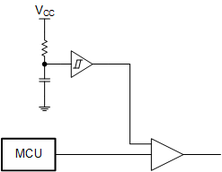
    The best option I can think of would be to use an SN74LVC1G125 and an SN74LVC1G17 + an RC for the enable time delay.

    The '126 has an active-high output enable pin, so you just have to keep OE low at startup to keep the output in high-impedance mode. It also has Ioff protection, so when the supply is off, the output will be in high-impedance also.

    The '17 is a Schmitt-trigger buffer, which allows for slow inputs (like from an RC circuit). You can select RC values to give enough delay that your device can turn on and start working before the output is enabled (I'd probably start with 1ms, which would be about 4.7kohm and 0.1uF).

    The circuit would look like this:

    Why a ST buffer? See: [FAQ] How does a slow or floating input affect a CMOS device?

  • The signal goes from the FT230 to the unpowered MCU, so simply using a buffer with an overvoltage-tolerant input (SN74LV1T34, SN74LVC1G125, etc.) will work just fine. (The input impedande does not change when powered down. The output impedance does not matter when both buffer and MCU are powered down.)

  • Thank you, will try it out.

  • Thank you, will try this out also.  Simple solution.