FAQ: Logic and Voltage Translation > Input Parameters >> Current FAQ
There are two primary issues associated with slow and floating inputs.
Not sure what a 'floating input' is? Please see our FAQ: What is a floating input or floating node?
(1) Shoot-through current
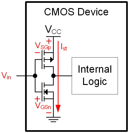
Figure 1. Typical CMOS input structure with the control voltage for each input MOSFET shown.
CMOS logic devices depend on their inputs being at either a logic HIGH or a logic LOW.
When the input is 'somewhere in the middle,' then it's easy to see from Figure 1 that both MOSFETs on the input can be turned on, which can cause a significant amount of shoot-through current. It is best to transition through this voltage region as quickly as possible to prevent shoot-through current.
This shoot-through current will cause additional power consumption, and can cause a reduction in reliability.
(2) Oscillation
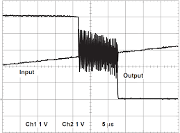
(Thanks to kai klaas69 for this image)
When the input lingers near the threshold value (typically 1/2*Vcc) then the output can oscillate between the LOW and HIGH state uncontrollably.
For any CMOS device that does not have Schmitt-trigger inputs, the datasheet defines a minimum input transition rate that will prevent this from happening.
The oscillations will cause additional power consumption, and can cause a reduction in reliability.
For more information, see the application report Implications of Slow or Floating CMOS Inputs


