This thread has been locked.

If you have a related question, please click the "Ask a related question" button in the top right corner. The newly created question will be automatically linked to this question.

DP83826E: Following Ethernet Debug Guide but still no link

Part Number: DP83826E
Other Parts Discussed in Thread: AM5708,

Hello TI Experts,

I'm currently working on a custom board from a customer, I try to get DP83826 working on the board.

The PHY is connected to an AM5708 with RMII signals. Straps are configured to have RMII Master by default, looks good on this point.

Basic device tree and other linux configuration already done and double checked.

Problem: I haven't any Link when connecting to the local network, whatever I'm connected to a switch or direct to my computer. Link up with loopback cable ok.

Trying to follow Ethernet Debug Guide at e2e.ti.com/.../Ethernet-Debug-Techniques.pdf, here is the checklist:
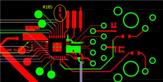
- Verify resistances:

RBIAS is 6.49k

No resistances on RMII signals between the PHY and the AM5708 (not sure it's really nice but don't know the impacts....)

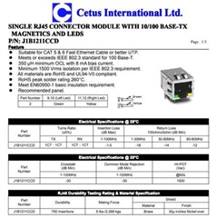
- Verify magnetic connection

Looks good

- Verify power rails:

VDD and VDDIO ok

RBIAS voltage seems floating near 0V => This is not normal but I don't know how to fix it !!
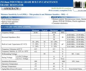
- Verify X1 clock:

25MHz ok

- Verify strap pins:

Looks good

- Probe TD+/- signal

With 100ohms terminated cable, I see the pulse

- Connection of loopback RJ45 cable:

Working, Link is up in kernel logs !!!!

- Registers:

Basic Mode Control Register (BMCR) Register Address 0x00h => 0x3100 => 100Mbps, AutoNegociation, Full-Duplex

Basic Mode Status Register (BMSR) Register Address 0x01h => 0x7849 => No link established

Auto-Negotiation Advertisement Register (ANAR) Register Address 0x04h => 0x01E1

Auto-Negotiation Link Partner Ability Register (ANLPAR) Register Address 0x05h => 0xCDE1

PHY Status Register (PHYSTS) Register Address 0x10h => 0x4102 => Seems to indicate MDI swapped (I'm connected to my computer so looks good) but at 10Mbps and Half Duplex only. Not sure how to interpret this...

Don't know where to go now and would sincerely appreciate any ideas that may go in the right direction for this problem !

Regards,

Joel

EDIT: after a while, registers 0x10 value is 0x5102, seems to indicate an inverted polarity but I don't know what the datasheet is speaking about (which polarity it is).

  • Hi Joel,

    What type of cable are you using for normal operation? Am looking for type and length. The RBIAS voltage seems normal. Can you please give me a register dump of register 0x0 to 0x1F, and 0x467, 0x468 during normal (no link) configuration and operation? In addition, can you please share your schematic for review? Can you also confirm what speed you are intending to run the connection at and if forcing the speed by disabling auto-negotiation helps?

    And to confirm, you are verifying no link by reading register 0x1 when connecting to your laptop or switch? Can you try other laptops and switches as well?

    I also wanted to confirm that you are currently still facing these issues. I see you have interfaced with Alon on a similar thread, so ensuring that we can consolidate if this is a duplicate post. 

    Sincerely,

    Gerome

  • Hello 

    First thanks a lot for the quick reply, I confirm this is the actual issue, the previous thread with Alon is different and we can say it's solved because it's not the actual problem.

    Regarding your questions:

    - Cable used is CAT5E and 2m long only. It's not damaged at all and perfectly working when I attached my laptop to the local network of the office for exemple so I know the cable is OK.

    - Schematic is attached (am5708 side and dp83826 part with the magnetics).

    - I have tried several computers, direct connection to RJ45 card, USB to ETH adapter, I attached to a local switch of the office => All of this conclude to no link (kernel logs and "ip link show" showing "NO-CARRIER"). When I connect the board to another independent switch and connecting my laptop to this switch as well (so only 2 ports used on the switch), then I got a Link Up on the board, ping is not stable at all and SSH impossible as describe above. Static IP addresses are used (10.38.96.1 on the board, 10.38.96.5 on my laptop). That's the best case I have.

    - Registers dump are attached:

    => registers_best_case.txt: This is done with cable connected to the switch (best case described above). I have started the board, cable is connected. You see kernel logs with "Link is up" but only 10Mbps. This is a Gigabit switch. DP83826 is 100Mbs capable so I except 100MBps. Then I do a small ping for testing - not stable at all - and then I'm using phytool to read registers. It seems phytool has difficulties to read 0x467 and 0x468 registers, not sure ?

    => registers_no_link.txt: This is done with direct connection between the board and my laptop. There is no link. Procedure is the same.

    - Disabling auto-negociation and forcing 100Mbps done and didn't helped.

    You say RBIAS voltage is normal ? Why ? I have checked the other post, but I don't understand the purpose of the RBIAS so ... I don't know what is it used for inside the PHY so I can't really have an opinion or technical understanding of the expected voltage. Isn't it a reference voltage for something inside the PHY ? Is it not used in this config ? I'm surprised because it's floating, it's not only 0V. It's very near to the crystal on th PCB and I see a small 25MHz signal on RBIAS, that's why I say it's "floating".

    Thanks a lot for the support,

    Joel

    EDIT: as indicated in the first message when I connect a loopback cable on the RJ45 port of the board, I immediately have "Link is up" log with 100Mbps/Full.

    Arago 2019.11 my-machine ttyS0
    
    my-machine login: root
    root@my-machine:~# ping 10.38.96.5
    PING 10.38.96.5 (10.38.96.5): 56 data bytes
    ping: sendto: Network is unreachable
    root@my-machine:~# phytool read eth0/1/0
    0x3100
    root@my-machine:~# phytool read eth0/1/1
    0x7849
    root@my-machine:~# phytool read eth0/1/2
    0x2000
    root@my-machine:~# phytool read eth0/1/3
    0xa110
    root@my-machine:~# phytool read eth0/1/4
    0x01e1
    root@my-machine:~# phytool read eth0/1/5
    0xcde1
    root@my-machine:~# phytool read eth0/1/6
    0x000f
    root@my-machine:~# phytool read eth0/1/7
    0x2001
    root@my-machine:~# phytool read eth0/1/8
    0000
    root@my-machine:~# phytool read eth0/1/9
    0000
    root@my-machine:~# phytool read eth0/1/10
    0x0100
    root@my-machine:~# phytool read eth0/1/11
    0000
    root@my-machine:~# phytool read eth0/1/12
    0000
    root@my-machine:~# phytool read eth0/1/13
    0x401f
    root@my-machine:~# phytool read eth0/1/14
    0x00a1
    root@my-machine:~# phytool read eth0/1/15
    0000
    root@my-machine:~# phytool read eth0/1/16
    0x0104
    root@my-machine:~# phytool read eth0/1/17
    0x010b
    root@my-machine:~# phytool read eth0/1/18
    0x4000
    root@my-machine:~# phytool read eth0/1/19
    0x6800
    root@my-machine:~# phytool read eth0/1/20
    0000
    root@my-machine:~# phytool read eth0/1/21
    0000
    root@my-machine:~# phytool read eth0/1/22
    0x0100
    root@my-machine:~# phytool read eth0/1/23
    0x0061
    root@my-machine:~# phytool read eth0/1/24
    0x0400
    root@my-machine:~# phytool read eth0/1/25
    0x8001
    root@my-machine:~# phytool read eth0/1/26
    0000
    root@my-machine:~# phytool read eth0/1/27
    0x007d
    root@my-machine:~# phytool read eth0/1/28
    0x05ee
    root@my-machine:~# phytool read eth0/1/29
    0000
    root@my-machine:~# phytool read eth0/1/30
    0x0102
    root@my-machine:~# phytool read eth0/1/31
    0000
    root@my-machine:~# phytool read eth0/1/1127
    0xffea
    root@my-machine:~# phytool read eth0/1/1128
    0xffea
    
    Arago 2019.11 my-machine ttyS0
    
    my-machine login: root
    root@my-machine:~# [   24.006187] cpsw 48484000.ethernet eth0: Link is Up - 10Mbps/Full - flow control off
    [   24.014040] IPv6: ADDRCONF(NETDEV_CHANGE): eth0: link becomes ready
    
    root@my-machine:~# ping 10.38.96.5
    PING 10.38.96.5 (10.38.96.5): 56 data bytes
    64 bytes from 10.38.96.5: seq=3 ttl=128 time=2.168 ms
    64 bytes from 10.38.96.5: seq=15 ttl=128 time=1.364 ms
    64 bytes from 10.38.96.5: seq=18 ttl=128 time=1.254 ms
    ^C
    --- 10.38.96.5 ping statistics ---
    20 packets transmitted, 3 packets received, 85% packet loss
    round-trip min/avg/max = 1.254/1.595/2.168 ms
    root@my-machine:~# phytool read eth0/1/0
    0x3100
    root@my-machine:~# phytool read eth0/1/1
    0x786d
    root@my-machine:~# phytool read eth0/1/2
    0x2000
    root@my-machine:~# phytool read eth0/1/3
    0xa110
    root@my-machine:~# phytool read eth0/1/4
    0x01e1
    root@my-machine:~# phytool read eth0/1/5
    0xcc61
    root@my-machine:~# phytool read eth0/1/6
    0x000f
    root@my-machine:~# phytool read eth0/1/7
    0x2001
    root@my-machine:~# phytool read eth0/1/8
    0000
    root@my-machine:~# phytool read eth0/1/9
    0000
    root@my-machine:~# phytool read eth0/1/10
    0x0100
    root@my-machine:~# phytool read eth0/1/11
    0000
    root@my-machine:~# phytool read eth0/1/12
    0000
    root@my-machine:~# phytool read eth0/1/13
    0x401f
    root@my-machine:~# phytool read eth0/1/14
    0x00a1
    root@my-machine:~# phytool read eth0/1/15
    0000
    root@my-machine:~# phytool read eth0/1/16
    0x5017
    root@my-machine:~# phytool read eth0/1/17
    0x010b
    root@my-machine:~# phytool read eth0/1/18
    0x6400
    root@my-machine:~# phytool read eth0/1/19
    0x6800
    root@my-machine:~# phytool read eth0/1/20
    0000
    root@my-machine:~# phytool read eth0/1/21
    0000
    root@my-machine:~# phytool read eth0/1/22
    0x0100
    root@my-machine:~# phytool read eth0/1/23
    0x0065
    root@my-machine:~# phytool read eth0/1/24
    0x0400
    root@my-machine:~# phytool read eth0/1/25
    0x8001
    root@my-machine:~# phytool read eth0/1/26
    0x0010
    root@my-machine:~# phytool read eth0/1/27
    0x007d
    root@my-machine:~# phytool read eth0/1/28
    0x05ee
    root@my-machine:~# phytool read eth0/1/29
    0000
    root@my-machine:~# phytool read eth0/1/30
    0x0002
    root@my-machine:~# phytool read eth0/1/31
    0000
    root@my-machine:~# phytool read eth0/1/1127
    0xffea
    root@my-machine:~# phytool read eth0/1/1128
    0xffea


  • Hi Joel,

    Some feedback:

    - I noticed that on your MDI circuit, you only have 1x 100nF per center tap. Please have 1uF and 100nF per center tap in order to meet datasheet recommendations.

    - Ensure integrated RJ-45 meets specs in table 12-2

    - How long are you MDI traces? Would recommend only having <2in

    - Ensure 10.2.3.2 and 10.2.3.3 section guidelines are followed

    - Ensure Xtal specs are meet according to table 10-1. Please also scope out CLKOUT signal to ensure frequency and PPM specs are met.

    - Can you confirm R180 and R181 are ferrite beads?

    - Rbias component is used to bias the internal circuitry within the PHY. In my initial post, there is a hyperlink to a thread regarding Rbias voltage.

    - For register 0x467, 0x468, extended register access is required. This is a 4 step register process using 0xD and 0xE.

    - Can you also please provide a scope capture of the RBIAS pin?

    - Can you provide layout around RBIAS pin?

    - Does adding a 2pF in parallel with RBIAS resistor help?

    Sincerely,

    Gerome

  • Hello Gerome,

    i have designed the custom PCB that Joel he's talking about.

    Ensure integrated RJ-45 meets specs in table 12-2:

    this connector seems compliant with the specifications.

    How long are you MDI traces? Would recommend only having <2in

    RD_M/P length are 7.9mm & 7.9mm

    TD_M/P length are 10.7 & 11.6mm

    they are all layouted on the same layer (Bottom) without any via

    Ensure 10.2.3.2 and 10.2.3.3 section guidelines are followed

    I asume that you think about the RMII & MDI layout Guidelines Sections

    The signals were layouted with a width of 0.1mm in paralelle of an adjacent perfect ground plan.

    Length of the diffrents signals are:

    • RMII0_CRS : 52.32mm
    • RMII0_REF_CLK : 56.26mm
    • RMII0_RXER : 54.74mm
    • RMII0_TXEN : 51.63mm
    • RMII0_TXD0 : 52.73mm
    • RMII0_TXD1 : 51.76mm
    • RMII0_RXD0 : 53.79mm
    • RMII0_RXD1 : 56.37mm
    • MDIO_MDCLK : 66.22mm
    • MDIO_D : 68.68mm

    Skew here is limited to few mm

    Some signals are layouted on different internals layers but there is always a ground plan adjacent for each signals.

    The RJ45 inclued Magnetics circuits & Metal Sheilds. The metal sheilds here is directly connected to the gnd of the PCB. I don't know if it is a problem.

    Ensure Xtal specs are meet according to table 10-1. Please also scope out CLKOUT signal to ensure frequency and PPM specs are met.

    I assume that this resonator fit with the specifications

    Can you confirm R180 and R181 are ferrite beads?

    yes i have measured on the PCB their values in DC with an ohmeter (values are are 0.3R).

    Can you provide layout around RBIAS pin?

    I’ll let Joel answer for the remaining questions

    Regards

    Romain

  • Hello

    Thanks for this analysis. Please find response below, hope this help to go further:

    - I noticed that on your MDI circuit, you only have 1x 100nF per center tap. Please have 1uF and 100nF per center tap in order to meet datasheet recommendations.

    => I have a 1µF initially (it's on the schematic below the red lines), but with this capacitor, situation is even worse : link up randomly appear with the loopback cable, and never never never append when connected to the laptop or the switch. Will try to put them back anyway (it will not solve the issue, they were mounted previously).

    - Ensure integrated RJ-45 meets specs in table 12-2

    => According to the hardware engineer of my customer it's ok (reference datasheet: http://wizwiki.net/wiki/lib/exe/fetch.php?media=products:wiz550web:wiz550webds_kr:j1b1211ccd.pdf)

    - How long are you MDI traces? Would recommend only having <2in

    => RD_M/P are 7.9mm and TD_M/P are 10.7 and 11.6mm respectively.

    - Ensure 10.2.3.2 and 10.2.3.3 section guidelines are followed

    => There is no section 10.2.3.2 and 10.2.3.3 in the datasheet I have, or maybe you have another one ?

    If you mean 10.2.4.2 and 10.2.4.3, this should be ok for the hardware engineer of my customer, we have: 

      • RMII0_CRS : 52.32mm
      • RMII0_REF_CLK : 56.26mm
      • RMII0_RXER : 54.74mm
      • RMII0_TXEN : 51.63mm
      • RMII0_TXD0 : 52.73mm
      • RMII0_TXD1 : 51.76mm
      • RMII0_RXD0 : 53.79mm
      • RMII0_RXD1 : 56.37mm
      • MDIO_MDCLK : 66.22mm
      • MDIO_D : 68.68mm

    - Ensure Xtal specs are meet according to table 10-1. Please also scope out CLKOUT signal to ensure frequency and PPM specs are met.

    => According to the hardware engineer of my customer it's ok (reference datasheet: https://abracon.com/Resonators/AWSCR_CW.pdf)

    - Can you confirm R180 and R181 are ferrite beads?

    => Yes they are.

    - Rbias component is used to bias the internal circuitry within the PHY. In my initial post, there is a hyperlink to a thread regarding Rbias voltage.

    => Yes I have checkout this.

    - For register 0x467, 0x468, extended register access is required. This is a 4 step register process using 0xD and 0xE.

    => Ok. Something I have not really realized before. Trying to do the procedure but result seems strange so please can you help using phytool ? I have done the following to read register 0x467:

    phytool write eth0/1/13 37

    phytool write eth0/1/14 1127

    phytool write eth0/1/13 4127

    phytool read eth0/1/14

    and same method for register 0x468, this give me REG 0x467 = 0x04a0 and REG 0x468 = 0x0000, which is not coherent I think...

    - Can you also please provide a scope capture of the RBIAS pin?

    => Attached:

    - Can you provide layout around RBIAS pin?

    => Attached:

    - Does adding a 2pF in parallel with RBIAS resistor help?

    => Added, no improvement. No significant changes on the RBIAS voltage.

    Thanks for the support,

    Joel

    PS : also just notice Romain answered in parallel:-)

  • Hi Joel,

    There appears to a potential issue with your strapping when decoding register 0x467. According to that, you are having pins 18, 13, and 22 be strapped high.

    However, the PHY is in basic mode, so the strapping changes with the mode. Pin 22 is not a valid strap and I therefore recommend ensuring the voltage is 0V during initialization of the PHY. Pin 13 is okay, as this is a test point and the pin has an inherent PU. For RMII master, pin 28 needs to be strapped high, while pins 29 and pin 18 need to either not be strapped or be strapped low.

    Can you please provide your intended strapping so I can double check the implementation in basic mode?

    Meanwhile, I am checking with the team regarding the RBIAS voltage issue.

    Sincerely,

    Gerome

    _______________________

    Edit 2/28/22: Modified for clarification

  • Hello

    You said "Pin 22 is not a valid strap and I therefore recommend removing that command" => which "command" do you mean ?

    You said "For RMII master, pin 28 needs to be strapped high, while pins 29 and pin 28 need to either not be strapped or be strapped low." => it's twice pin 28 :-) probably a typo error, can you fix ?

    The intended configuration I would like is a basic Ethernet connection working. BASIC mode, 100Mbs/s. I'm not configuring anything. Purpose is to do SSH to the target, that's all at the moment. Currently the DP83826 is wired as shown on the piece of schematic I have shared above:

    - Mode select is connected to ground

    - RESET is driven by the power supply directly (not by the AM5708)

    - RMII signals connected to AM5708 (no pull-up or pull down anywhere)

    - Magnetics connected directly with 100nF capacitor at the denter tap (C218 and C224)

    - 25MHz crystal

    - RBIAS 6k49

    - CEXT 2.2nF

    - Pin 21 has a pull up and no other connection

    - Pin 28 has a pull up and no other connection

    - Pins 29 / 30 and 31 are not connected

    - TXCLK, TXD2, TXD3, RXD2, RXD3 are not connected

    I really don't understand what is wrong here unfortunately, even after checking and checking again...

    We haven't spoken of the software part, it's currently based on Processor SDK 06_03_00_106, with kernel 4.19. Support of the DP83826 was not available, I have added support to the existing DP83822 driver (basically adding the new entries as done on the 5.10 kernel where the DP83826 is supported). Device tree is updated to add the DP83826, using RMII + MDIO signals. Anything we should check on this part based on the symptom of the issue ?

    Thanks a lot for the support, I sincerely appreciate,

    Regards,

    Joel

  • Hi Joel,

    Regarding strapping, it can happen that there may be an unintended voltage on the line during sampling which can cause the PHY to go into an undesired mode. I would recommend taking a volt meter and probing the strap pins in question to ensure that they are not being unintentionally strapped. 

    In addition, regarding the extended read/write procedure, please follow below:

    Reg 0xD = 0x1F

    Reg 0xE = *Address of register outside of 0-1F you are trying to read (in this case 0x467, 0x468)*

    Reg 0xD = 0x401F

    *Read Reg 0xE for value. This is what is within the register you first wrote into Reg 0xE

    In your case, the strapping should be the following:

    - RX_D3, RX_D2, RX_D1: Strapping dependent on PHY address. Corresponds to Reg 0x467[9:7]

    - COL = '1', CRS = '0', RX_DV = '0': RMII Master mode. Corresponds to Reg 0x467[4, 3, 10 respectively]

    - LED0 = '1': Auto-Negotiation enabled. Corresponds to Reg 0x467[2]. See Reg 0x0[12] as parallel confirmation of bit

    - TX_ER/LED1 = '1'. Advertise 100Mbps speed. Corresponds to Reg 0x467[1]. See Reg 0x4[8:5] 

    - RX_D0 = '1': Advertise full-duplex. Corresponds to Reg 0x467[0]. See Reg 0x4[8:5] 

    - RX_ER = '0': MII Isolate Disabled. Corresponds to Reg 0x467[6]. See Reg 0x0[10] 

    Also, RBIAS voltage should be around 0V. Am checking if the coupled waveform is an issue.

    Also, can you please confirm via CLKOUT pin of PHY to confirm ppm is okay? See Reg 0x304 on how to configure LED1 to CLKOUT. This waveform should have ppm under +/- 100. I do see that load capacitance and ESR does violate datasheet recommendation (See table 10-1).

    Sincerely,

    Gerome

  • Hello ,

    Thanks for the reply.

    What you point for the crystal is interesting for me, it seems the tolerance is 0.5% = 5000ppm, out of the spec required by the PHY you're right!

    I have not output the clock on the CLKOUT pin, but quickly measured the frequency at the crystal and result is 25.03MHz. Inside the crystal specifications but outside the requirements of the PHY.

    Is it possible that the bad tolerance of the crystal lead to a bad link when connected to another computer and a good link when doing a loopback ? I mean : this seems reasonable thinking for me because the bad tolerance in this case probably don't impact the synchronization, has it is used for Tx and Rx?

    Question : do you have a good reference design for Ethernet application using the DP83826 ? I have checked DP83826EVM (https://www.ti.com/tool/DP83826EVM, https://www.ti.com/lit/ug/snlu262/snlu262.pdf), is it good starting point or maybe do you have another one too ?

    DP83826EVM has "ECS-250-12- 33Q-JES-TR" crystal + 2x 22pF capacitors. Is it the recommended wiring for the crystal on the DP83826 ?

    Thanks for the support, I appreciate your help :-)

    Joel

  • Hi Joel,

    Yes, usually for link and packet issues, checking the clock source is one of the primary suspects. 

    DP83826EVM is a great starting point for a reference design. 

    Yes, this is the recommended wiring. You solution would match this configuration as well (aside from the series resistor on XO) if the specifications on table 10-1 would be met.

    Sincerely,

    Gerome

  • Hello

    Thanks for the confirmation. Crystal has been ordered in the meantime, should arrive tomorrow or the day after, I will do the modification on the PCB by the end of the week and report the result here.

    Joel