This thread has been locked.

If you have a related question, please click the "Ask a related question" button in the top right corner. The newly created question will be automatically linked to this question.

DS90UB960-Q1: Sync issue

Part Number: DS90UB960-Q1


Hi team,

My customer has encountered an issue of 935-960.

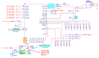
DS90UB960 connects three DS90UB953, in them two cameras are in synchronous mode, and another one uses an external clock in asynchronous mode. The camera in the external clock asynchronous mode is dropping frames. Will it be a problem to use this way?

  • Hi Zirui,

    What forwarding mode is being used on the UB960? And is FrameSync being sent to the connected serializers? If so, is it internally generated or externally generated FrameSync?

    Best,

    Justin Phan

  • Hi Justin,

    The sync I mean is about the clock mode, that is to say the 2 of the 3 camera 953 uses clock sync mode which referring to the 960 clock source and another one is referring to the 953 itself external clock, I think customer is using 960 round robin output mode, do you think it will be OK with such configuration and combination? Besides, if customer uses 960 sync output mode, do you think it is also ok? Thank you!

  • Hi Zirui,

    It is possible to set each Rx Port of the UB960 device to operate at a different MODE. Once CSI-2 mode is set at power-up of the UB960, Synchronous mode is selected for all RX ports be default. But the customer can select one of the RX Ports, by setting the appropriate RX_WRITE_PORT bit in register 0x4C, and then configure it for Non-Synchronous mode.

    And the UB960 is able to aggregate all of the video data from the 3 connected serializers, with no issue, as long as you can LOCK to each serializer and properly recover the sent video data. Round robin mode retrieves video lines stored at each RX buffer and forwards them to the CSI-2 output port. In this mode, there is no requirement on the cameras and no requirements on synchronization.

    I see no issue in the customer setup.

    If the customer wants to use a synchronized forwarding mode, then the cameras will need to be the same resolution and have synchronized frames. See Section 7.4.25 CSI-2 Forwarding in the UB960 datasheet for more details and requirements.

    Best,

    Justin Phan

  • Hi Justin

    Thanks for your reply. Now my customer has encountered an issue reflecting by the camera side which said 'LINE_LEN_UNSTABLE', I told them check 953 if it has CSI-2 error while customer told me there is no CSI-2 error read by 953 register. The 960 is using round-robin output mode, the 953 resolution is 2560*720@30fps.

    953 schematic:

    (The red word means in order to pass EMC test, customer NC the crystal)

    Here is their 960 schematic using round-robin mode:

    960 video in1.pdf

    Please kindly check if customer's schematics are not proper to cause the LINE_LEN_UNSTABLE and the shown picture freezes with dropped frame issue, thank you.

  • Hi Zirui,

    1) Could your customer first confirm that the UB960 is LOCKed with each connected serializer? First, select one of the RX ports by setting reg 0x4C[5:4] in the UB960 device. Then, read register 0x4D. Do this for each RX Port and confirm reg 0x4D[0] = 1 for each RX Port.

    2) Could your customer confirm that there are recurring errors detected by the UB960 device. First, select one of the RX ports by setting reg 0x4C[5:4] in the UB960 device. Then, read registers 0x4D and 0x4E. Since these register bits clear on read, I'd also like for the customer to wait about 10 seconds after the first read and then read these registers again.

    3) On the UB953 that is suspected to be sending CSI-2 packets with errors to the UB960, could you do the same read reg, wait 10 seconds, and then read again on the following registers:

    I would like to make sure if the UB953 is detecting incoming CSI-2 errors.

    Best,

    Justin Phan

  • Hi Justin

    Thanks for your reply from register aspect. We also would like to know whether customer's schematic design has some problems? Could you please kindly help us to review it? Thank you!

  • Hi Zirui,

    Here are my comments on the UB953 schematic that was shared already:

    1) The I2C pull-up resistors on the SCL and SDA lines are not shown. Make sure to select optimum pull-up resistors, based on the I2C data rate and bus capacitance on the customer's PCB board, by referring to App Note SLVA689.

    2) The UB953 chip only has 32 pins + DAP, so I'm not sure why there are more pins beyond that, which are tied to GND.

    3) There is a 10-kOhm pull-up resistor to 1.8V on the MODE pin. This doesn't match the strap setting defined in the Strap Configuration Mode Select table in the UB953 datasheet. Recommend to follow the suggested resistors in the table, to select a MODE.

    4) The Ferrite Beads used on the VDDD, VDDDRV, and VDDPLL pins must have the following characteristics:

    Z=1-kOhms@100MHz

    DCR<=500-mOhms

    The EVM uses BLM18AG102SN1D. Recommend to use the same or similar part.

    And for the UB960 schematic, I will review that and provide comments within ~1 week.

    Best,

    Justin Phan

  • Hi Justin,

    Thanks for your reply. Here I also discussed with customer for your questions:

    1. Double check that their I2C has 2.2k pull up resistors;

    2. In 953 schematic like pin 33, it is the heat dissipation pad pin in the middle of the chip;

    3. In the early stage of the project, it was carried out according to the design of the asynchronous mode and the external crystal. However, during the EMC test of the whole system, it was found that the frequency doubling interference of the external crystal oscillator would cause the radiation test item to exceed the standard. After the continuously functional test of the template with removing the external crystal, no abnormality occurred, therefore the external crystal was determined to remove from the previous design;

    4. Double check the ferrite beads spec:

    Question from customer side:

    1. Does the chip automatically switch to the internal crystal if after it does NOT detect the external crystal? The internal crystal is 26Mhz by default. At that time, customer tried to configure it as 26M and 52M respectively, and the display was normal under each crystal setting. What aspects of FPD-Link will be affected by the configuration of these two frequencies?

    2. Customer may take the improper 953 reference like below:

    Rather than:

    The question is If we want to use Non-Synchronous internal Clock mode, could we just configure it via register rather than modifying the schematic hardware design? I check in 953 datasheet found the 0x03 register, but I did not find the Non-Sync with internal clock mode (just found non-sync with AON clock), I see it could overrides strapped value, so I think it could work without modifying the hardware schematic design. Could you please kindly help to let us know how to configure Non-Synchronous internal Clock mode? Thank you.

  • Hi Zirui,

    Here are my responses:

    3. Make sure to update the resistors on the MODE pin, to match the desired MODE at power-up.

    4. The Ferrite Bead used in the schematic (MPZ1005S121CTD25) does not meet the required Ferrite Bead characteristics. Our UB953 EVM uses BLM18AG102SN1D. Recommend to use the same or similar part.

    Here are my responses to the questions:

    1.  The internal reference clock is between 24.2MHz to 25.5 MHz, as defined in the datasheet. Register 0x04 can be used to configure the internal reference clock. If the external clock input frequency is below the limit or missing, then the internal clock will be automatically used instead. This situation only applies if you are configured for Non-Synchronous External Clock Mode. If you lose external clock input, then the device switches to Non-Synchronous Internal Clock Mode.

    If you configure the internal clock to be about 25MHz, then the Forward Channel line rate will be about 2Gbps. If you configure the internal clock to about 50MHz, the Forward Channel line rate will be about 4Gbps. The Forward Channel frequency affects the video throughput allowed from the Ser/Des. See the section below for more details:

    All qualities of the clocking modes are summarized in this table:

    It seems your CSI-2 input is within the CSI-2 bandwidth allowed. 

    2. You can change the MODE setting through registers without modifying the hardware design, by changing register 0x03[2:0] to Non-Synchronous Internal Clock Mode. AON clock stands for Always-On-Clock and is the same as the internal clock.

    Best,

    Justin Phan

  • Hi Zirui,

    Attached is my comments on the UB960 schematic. Let me know if there are any questions.

    960 video in1 - Reviewed.pdf

    Best,

    Justin Phan