


Part Number: TPS25750
Hello,
I designed a board as 15V USBC sink using TPS25750D.
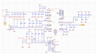
Now after manufacturing the boards I am stuck on a problem. The USBC supply simply won't work.
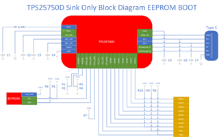
According to this forum topic https://e2e.ti.com/support/interface-group/interface/f/interface-forum/988215/faq-tps25750-how-do-i-create-a-sink-only-usb-c-pd-port-to-replace-a-legacy-barrel-jack-connector I should connect PP5V to GND when using TPS25750 as sink only.
1. Error description:
When the Eeprom is not programmed I get 5V on VBUS.
The moment I programmed the eeprom and plug in the USBC the 5V will turn off every ~750ms.
PPHV is never activated. I can measure about 200mV on those pins.
The used CCy pin will go up to ~1,6V (same as Eval board) and tries to negotiate the voltage. Shortly before the 5V supply is switched off, the voltage on CCy jumps to 4V.
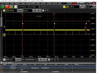 (CCy on my board)
2. Differences between my Board and the evaluation module:
- all GPIOs are tied to GND as described in the datasheet pin description.
- PP5V is tied to GND as described in the forum entry.
- VIN_3V3 is not present.
- I am using a PD only USBC socket. It only has VBUS (2x), GND (2x) and the two CC pins. No data lines available.
there must be a differemce which I am missing but I can't seem to figure out what it is.
3. Tests I already did:
- Evalboard: Shorten PP5V to GND (same as on my board) à still works and I get 15V with the same bin-File.
- Evalboard: Shorten all GPIOs to GND (same as on my board) à still works and I get 15V.
- Evalboard: Remove the 3V3 supply jumper from VIN_3V3. à still works and I get 15V.
- My board: Track the I2C communication between TPS25750 and Eeprom. à the slopes look good and the data I can read on the scope is the same as in the bin-File.
- My board: voltage on CCy pin. See attached image. I do not understand why the voltage goes up to 4V.6. My board: I tried a different USBC power supply.--> same problem.
- added more capacitance in VBUS (40µF instead of 20µF) --> no difference
- I tried different settings an bin-Files. 5V - 3A sink only; 15V 3A - sink only, 9V - 3A device --> always the same. It works on the evaluation board but not on mine
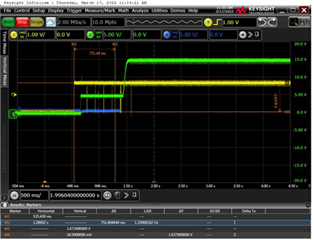
- compared startup on both boards (15V 3A sink only bin-File)
 (Startup Evalboard)
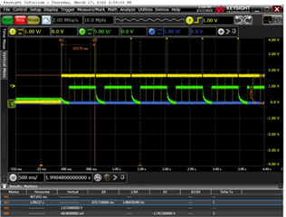 (startup my board)
yellow: CCy
blue: PPHV
green: VBUS
Have you encountered this problem before and can help me solve it?
Thanks in advance.
