Because of the Thanksgiving holiday in the U.S., TI E2E™ design support forum responses may be delayed from November 25 through December 2. Thank you for your patience.

This thread has been locked.

If you have a related question, please click the "Ask a related question" button in the top right corner. The newly created question will be automatically linked to this question.

SN65HVD3085E: UART to RS485 can't working correctly

Part Number: SN65HVD3085E

Hi Sir,

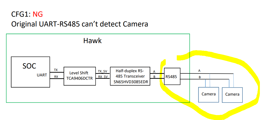
Our end customer feedback they met the RS485 issue of the cameras connect to our MB’ UART-RS485 port aren't been detected.

I attach the details in the attachment with the waveform we measured in yesterday, could you provide your recommendation of how to fix the issue?

Rds,

Joyce


RS485 issue-0322Y22-1.pdf

  • Hi Joyce,

    Thanks for reaching out!

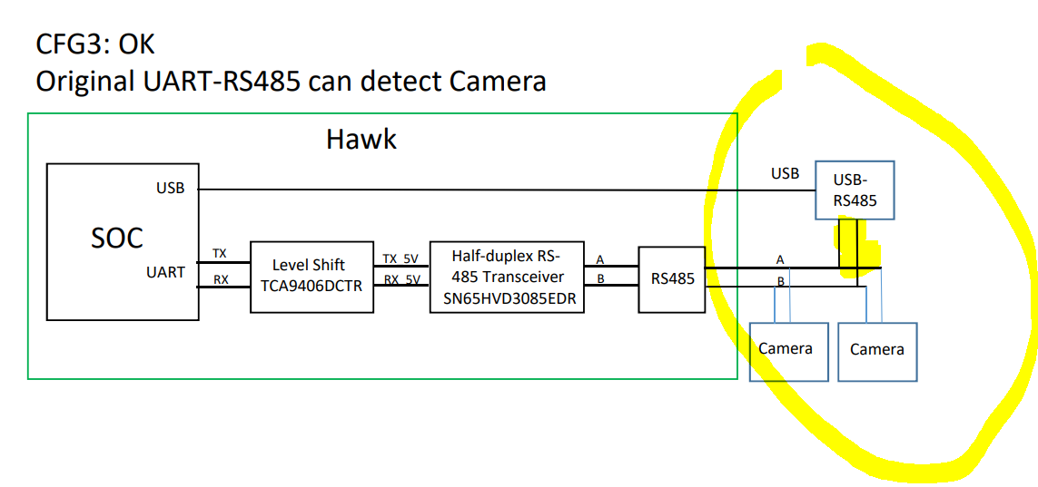
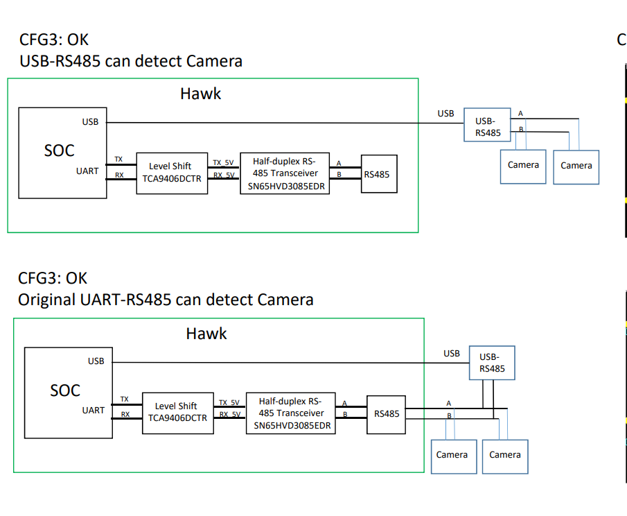
    So after looking through the slides it seems that only 1 configuration is failing and the other's seem too be working. If the scope shots are all on the SN65HVD3085E A/B pins in all cases and it is the same part there is most likely implementation difference that is causing the issue.

    With that being said I do have a few questions so I can help pin down what could be causing these issues. 

    1. How are the Camera's connected in the following configurations:

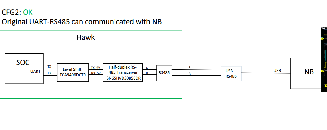
    2. What is the output connected to in configuration 2? As there doesn't seem to be problems on this one either. 

    Overall it looks somewhat like a loading issue on the A/B lines in configuration 1 - but not in 2 or 4 (which have slightly different loading) - so ultimately if you can share the differences in loading as that seems the most likely area where problems could pop up based on what you have provided.

    Please let me know!

    Best,

    Parker Dodson

  • Hi Sir,

    I just receive the schematic of Camera.

    it is using 3.3V RS485 transmitter. is it okay for this application?

    Rds,

    Joyce

  • Hi Joyce,

    The difference in voltage supply shouldn't be an issue as the A/B pins of all RS-485 devices should be rated to at least -7V to 12V on those pins to handle the RS-485 Spec on common mode voltages.

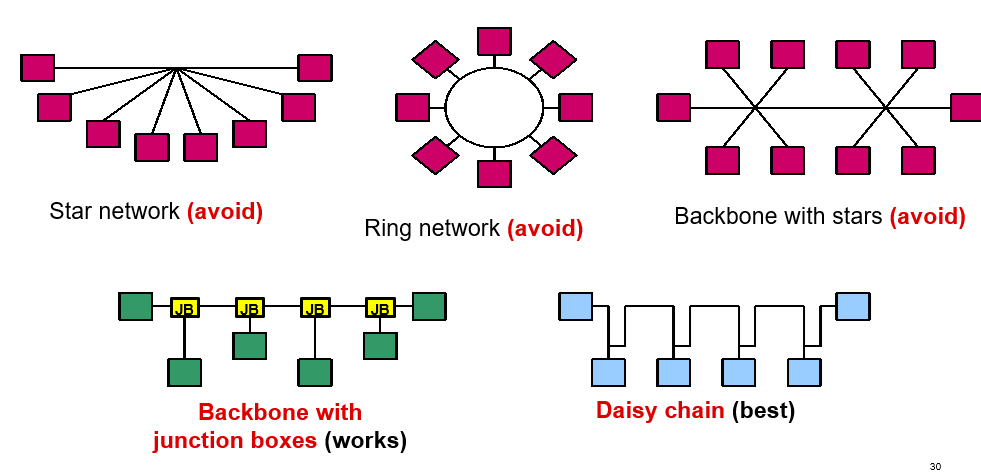
    That being said - the lack of a terminating resistor  on the camera could be causing issues as it could be producing reflections that could be detrimental to the signal. The two far ends of the RS-485 transmission line need to be terminated (ideally 120 Ohm Characteristic Impedance of the Transmission line + 120 Ohm resistors on both sides of the bus. This 1) lets the driver see 60 Ohms (max loading on RS-485 Transceiver to be in spec is 54 Ohms) and 2) the reflections in an ideal scenario are 0% of the original signal (due to tolerance there will be some reflections regardless). Since it looks like there is more than 1 camera on the transmission line - only the farthest camera from the main board needs to be terminated - but how the devices are connected also matter:

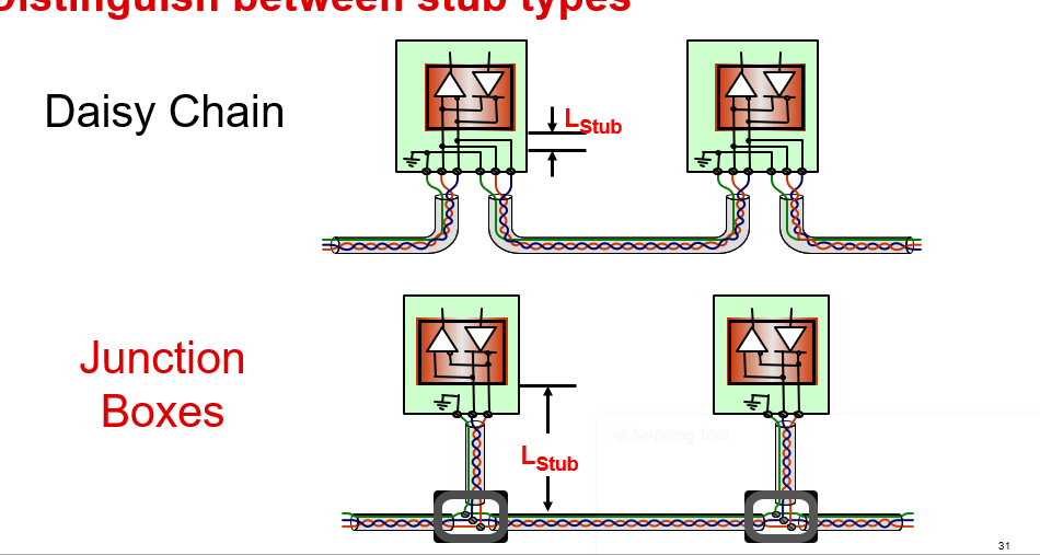
    Depending on how the devices are connected together the stubs themselves could also be contributing to reflections. Where v is the signal speed on the conductor (less than C due to capacitance on line) and c is the speed of light. Typically v ~75% - 77% but this largely depends on the actual cable used. Let's assume a v value of 75.5%. For this device (t_r is typically 200ns)  that means the max stub length is going to be  L_Stub <= 200ns/10 * 0.755 * 9.8*10^8 ft/s --> ~14.8ft max stub length for this device assuming v ~75.5%

    However - the problem comes with the configuration. 

    What is different, from a schematic level, on both plots labeled configuration 3? 

    How does the USB-RS485 to camera connection look? Because in both of these scenarios the device worked.

    Also what does Configuration 2's schematic look like?

    I have a feeling it is just an implementation error, but I want to see what schematic level changes were made in the cases where the device works. Also if you could provide length between the main board and the cameras, the cable being used and its parameters, as well as the data rate of the application I will be able to better judge if it is just reflections on the lines causing issues.

    So in conclusion:

    I do think reflections are a prime suspect of the issue - and this is largely dependent on the implementation. If you could provide the following:

    1. Data rate of application

    2. Length of transmission line from Main board RS-485 to Camera RS-485. As well as the transmission line parameters or just the cable's part number that they are using.

    3. Schematic Level changes when the USB-RS-485 part is being used -since this configuration works a good idea is to look what is different on the transmission line in these cases. (Both plots labeled configuration 3 in original document) 

    4. Schematic level changes for configuration 2 (compared to configuration 1). This is to see what is different between the two implementations at a schematic level.

    5. Confirm if either of the camera's are terminated.

    6. Confirm how the devices are wired on the bus (topology) - and if stubs are used their length. 

    I do think this is most likely a signal integrity issue due to direct implementation issues - if you could provide the above information I will be able to narrow down possible problem areas that need corrected.

    Best,

    Parker Dodson

  • Hi sir,

    could you sharing the reference design of how to auto switch DE, RE pins?

    Does it work of below circuit to use RX232 Tx?

    Rds,

    Joyce

  • Hi Joyce,

    The auto-detection circuit you show will not work as it will end up toggling the enables with every bit transition.

    Please see application note on automatic direction control - https://www.ti.com/lit/ug/tidubw6/tidubw6.pdf?ts=1649864941377&ref_url=https%253A%252F%252Fwww.ti.com%252Fsitesearch%252Fen-us%252Fdocs%252Funiversalsearch.tsp%253FlangPref%253Den-US%2526searchTerm%253Dauto%2Bdirection%2Brs-485%2526nr%253D831

    Essentially the way to do this is to use a 555 timer with the output connected to the enables, the trigger being data on the "D" line, and the timer to be set to the duration of the data frame so that all the data is properly handled. This design works only with applications that have fixed packet lengths as the data frame is set before operation. 

    Please let me know if you have any other questions!

    Best,

    Parker Dodson