This thread has been locked.

If you have a related question, please click the "Ask a related question" button in the top right corner. The newly created question will be automatically linked to this question.

DP83869HM: DP83869 SYNE

Genius 11430 points
Part Number: DP83869HM
Other Parts Discussed in Thread: DP83869

Hello TI experts

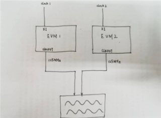
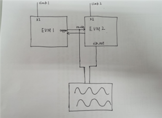
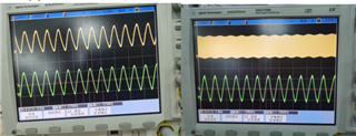
Our customers wanna to know what kind of configuration do I need to configure the chip or register of the DP83869 to implement the SYNC-E function, is its recovered clock output pin rx_clk? And what is the frequency synchronization accuracy it can achieve (what is the standard deviation). 

Thank you very much!

Best Regards,
William

  • Hi William,

    You can program reg<0x170>[12:8] = 0x04 to get 25MHz syncE clock on CLK_OUT pin of the device.

    Let me check the frequency accuracy and get back to you.

    --
    Regards,
    Gokul.

  • Hi  Gokul,

    Do you mean that the recovered clock of SYNC-E is output through the clk_out port? If I need a 125MHz clock, do I just need to set reg<0x170>[12:8]=0x00? thank you for your reply

    Best Regards,
    William

  • Hi William,

    Yes, you can use the 125MHz clock too by programming reg<0x170>[12:8]=0x00.

    --
    Regards,
    Gokul.

  • Hi  Gokul,
    Thank you for your reply. I still have two questions that I hope you can answer. One is how accurate the SYNC-E frequency synchronization of the DP83869 can be? The second point is that RX_CLK is sure not to recover the clock, right? Because in another Q&A it gave a reply that RX_CLK can be used as a recovered clock, which I actually tried and didn't work, I'm curious.
    Thanks!
    Best Regards,
    William
  • Hi Jiashui,

    RX_CLK will be recovered clock in Slave mode(MDI side) which can be used as SyncE clock and master clock in Master mode (MDI side). I guess the device is in Master mode and it didn't work.

    You can use CLK_OUT with the above register writes for always getting recovered clock independent of Master/Slave.

    Let me check on the accuracy and get back to you.

    --
    Regards,
    Gokul.

  • Hello,Gokul.
    Thanks for your quickly reply , our customers has still other question:
    I tried to change the register of reg<0x170>, but there is no good way to make sure that my change is successful, the software I use cannot access the extended register, and the value read is wrong. The way I change the register is to change it through the driver. The official driver and the device tree suggestion have pointed out how to change it. Through the printing information in the driver, I can observe that reg<0x170>=0 This should be the correct value, but no matter I How to change the register, the value I get by measuring clk_out is always 25MHz. At the same time, I tried changing reg<0x9> and reg<0x10> to MDI slave mode, but the clock recovered by rx_clk still has no obvious effect.
    Based on the above, there are two questions I would like to ask you:
    1. Is there any way to read and write the extended register information of the PHY chip in the embedded system?
    2. If I want to change rx_clk to a recovered clock, how do I configure the registers?
    Thank you advance!
    Best Regards,
    William
  • Hello William,

    You can program the extended register using the way described below

    eg., you want to program (MMD,ADDR) = (1F,YYYY) and data = ZZZZ then program

    Write 0x000D = 0x001F
    Write 0x000E = 0xYYYY
    Write 0x000D = 0x401F
    Write 0x000E = 0xZZZZ

    eg., you want to read (MMD,ADDR) =(1F,YYYY)

    Write 0x000D = 0x001F
    Write 0x000E = 0xYYYY
    Write 0x000D = 0x401F
    Read 0x000E

    You mention that there is no obvious effect when you changed the device to slave. Since both the clocks are 25MHz, you can't visually see any change. Did you measure the jitter to see if the jitter profiles changed?

    --
    Regards,
    Gokul.

  • Hello,Gokul.

    Our customer has reply below:

    PS: When I connect with the network, the following prompt will be displayed on my serial port debugging assistant:

    macb e000c000.ethernet eth0: unable to generate target frequency: 125000000 Hz

    macb e000c000.ethernet eth0: link up (1000/Full)

    IPv6: ADDRCONF(NETDEV_CHANGE): eth0: link becomes ready

    I'm not sure if this affects its recovered clock?

    Thank you very much!

    Regards,
    Gokul.

  • Hello,Gokul.

    I am sorry that please ignore above information ,Our customer has reply below:

    through the method you provided, I read the value of the chip reg<0x170>, and I can get the value that is exactly what I need, which is 0x0, but the clock signal I get by measuring the clk_out pin is always 25MHz, not I need 125MHz. I tried setting the value of reg<0x170> to 0x400 and 0x800, which represent 1/5 of the recovered clock and the transmit clock, respectively, however, the clock I measured on the clk_out pin remained at 25MHz. Can I ask what could be the reason for this? I will measure some basic register information to analyze, I hope you can make some suggestions.
    PS: I only apply the rgmii-to-copper mode now
    (The measurement of the 25MHz clock has nothing to do with the MDI slave mode. When I set it to the MDI slave mode, the recovered clock used is RX_CLK instead of CLK_OUT, but this method also does not work, I still need to know what syncE can achieve. frequency synchronization accuracy)
    The following is the value of the register I measured, I hope it will work
    ADDR  value same as reset
    0  1140
    1  7949
    2  2000
    3  a0f1
    4  01e1  x
    5  0000
    6  0066  x
    7  2001
    8  0000  x
    9  0a00  x
    a  0000
    d  401f 
    e  0800
    f  f000 
    10  5048
    11  1002  x
    12  0000
    13  1dc4  x
    14  29c7
    15  0000
    16  0000
    17  0040
    18  6150
    19  4444
    1a  0002
    1e  0012
    1f  0000
    extend
    25  0480
    2C  141f
    32  00d0
    6e  0000
    170  0800
    1df  0000
    1E0  417A

    PS: When I connect with the network, the following prompt will be displayed on my serial port debugging assistant:

    macb e000c000.ethernet eth0: unable to generate target frequency: 125000000 Hz

    macb e000c000.ethernet eth0: link up (1000/Full)

    IPv6: ADDRCONF(NETDEV_CHANGE): eth0: link becomes ready

    I'm not sure if this affects its recovered clock?

    Thank you very much!

    Regards,
    William

  • Hi William,

    Let me try the same here locally here and get back to you by Wednesday.

    --
    Regards,
    Gokul.

  • Hello,Gokul.

    Thank you ,I will wait your reply .

    Thanks again!


    Regards,
    William

  • Hi William,

    Can you please let me know the final use case of SyncE? Is the customer interested in 25MHz recovered clock or 125MHz recovered clock?

    Is the clock expected on CLKOUT? 

    I can specifically test this condition out in the lab to see of the expected behavior is observed.

    --
    Regards,
    Gokul.

  • Hello,Gokul.

     Yes, I need to get SYNCE's clock to use as a marker for my IEEE1588 clock synchronization hardware timestamp; I have solved the problem of CLK_OUT port generating 125MHz clock according to another question and answer.

    According to your description, there are two ways to obtain the SYNCE clock: 1. The CLK_OUT port restores the clock; 2. The RX_CLK restores the clock, but the mode needs to be changed to MDI slave mode.

    I can't try the first method for the time being, because I don't have a trace set to bring the clock to my board; I tried the second method, but I didn't get the results I wanted; and set the master to manual MDIX; the slave After setting to manual MDI, the packet loss rate of communication between them went up.

    At this stage, I am re-designing the plate to introduce the clock obtained from CLK_OUT into the board; the help I want to get from you is: 1. How to correctly configure the second method to obtain the SYNCE recovered clock? 2. What kind of frequency synchronization accuracy can the SYNCE clock recovered by DP83869 achieve?

    Thanks for your answer!

    Regards,
    William

  • Hi William,

    You mentioned you need the accuracy in terms of standard deviation, correct? In the datasheet, we have the accuracy in terms of jitter. I don't have the standard deviation currently and will have to collect that data tomorrow. 

  • Hello,Gokul.

    Okay, thanks for your information , it is our pleasure to have you in TI company
    Regards,
    William

  • Hi William,

    Thanks! I will provide the information by end of today.

    --
    Regards,
    Gokul.

  • Hi William,

    The standard deviation of SyncE clock in the worst case is ~100ps.

    --
    Regards,
    Gokul.

  • Hello Gokul

    Yes, I need to get SYNCE's clock to use as a marker for my IEEE1588 clock synchronization hardware timestamp; I have solved the problem of CLK_OUT port generating 125MHz clock according to another question and answer.

    According to your description, there are two ways to obtain the SYNCE clock: 1. The CLK_OUT port restores the clock; 2. The RX_CLK restores the clock, but the mode needs to be changed to MDI slave mode.

    I can't try the first method for the time being, because I don't have a trace set to bring the clock to my board; I tried the second method, but I didn't get the results I wanted; and set the master to manual MDIX; the slave After setting to manual MDI, the packet loss rate of communication between them went up.

    At this stage, I am re-designing the plate to introduce the clock obtained from CLK_OUT into the board; the help I want to get from you is: 1. How to correctly configure the second method to obtain the SYNCE recovered clock? 2. What kind of frequency synchronization accuracy can the SYNCE clock recovered by DP83869 achieve?

    Thanks for your answer!

    Regards,
    William

  • Hello Gokul
    Sorry for last email, it is duplicate , please ignore it . please kindly help to resolve the query below:
    thank you very much for your help with the test!
    I hope I can get the same standard deviation, so I would like to ask about your test plan, and the specific configuration method, thank you!
    Regards,
    William
  • Hi William,

    For my test, I linked up 2 DP83867 EVMs with their input clocks from different sources with some frequency offset.

    I got the 125MHz recovered clock on CLK_OUT pin and measured the TIE of the clock output using oscilloscope.

    --
    Regards,
    Gokul.

  • Hello Gokul
    Thanks for your reply!
    However, I don't quite understand what you mean, do the clocks connected to the two EVM boards come from different clock sources? As shown in Figure 1 below, are the two communicating?
    From what I understand, the two EVM boards should be connected as shown in Figure 2 below.
    Or are you setting the registers differently for the two CLKOUTs?

    I understand that the recovered clock is recovered from the RX_CLK in the network. Is my understanding wrong?

    Regards,
    William

  • Hi William,

    Sorry for the confusion. The first image you have shown is the setup I used for testing.

    I was talking about the inputs to XI, which are clk1 and clk2 which are from different external sources which have ppm offset.
    For now, you need not use different clocks and use the crystals for the clock sourcing.

    --
    Regards,
    Gokul.

  • Hello Gokul
    Thanks for your reply.
    According to your explanation, I do not understand the following points:
    1. When you tested, did the two EVM boards not communicate through the network port?
    2. What are the reg<0x170> of the two EVM boards?
    Meanwhile, I tested according to my test scenario:
    First, I used two DP83869 boards, and the clock source used their own clock source; and got the 125MHz clock in the following way:
    0xD10 -> reg<0x170>
    0x10 -> reg<0xC6>
    Here is the solution to the previous question that you can't generate a 125MHz clock;
    Then, I connect the two boards through a network cable to realize communication, and set the reg<0x170> of board 1 and board 2 to 0x800 and 0x0 respectively;
    Finally, I run the following two tests separately through the oscilloscope:
    1. In the case of network cable connection, test the delay time of the two clocks;
    2. When the network cable is disconnected, test the delay time of the two clocks;
    The following Figures 1 and 2 are obtained;
    Based on the above test, I would like to ask you two questions:
    1. Whether test 1 can indicate the SYNCE recovery clock of the DP83869 board;
    2. In Figure 2, the two clocks cannot be stable at the same time. What is the reason? Is it because of inconsistencies in frequency?
    Is my test plan correct?
    Thank you for such a responsible reply!
    Regards,
    William
  • Hi William,

    From what I understand, you are measuring the delay between transmit/recovered clock or board-1 vs recovered/syncE clock of board-2.

    When the cable is connected between them and the boards are linked-up, all the frequencies are made to align and hence you see a fixed delay.
    When the cable is disconnected, the alignment of clocks of board-1 and board-2 doesn't happen. This is due frequency mismatch between both the boards. Any small frequency offset will make the clocks look asynchronous to the naked eye.

    So, overall, I think you were able to observe what is intended in your system.

    --
    Regards,
    Gokul.

  • Hello Gokul
    Thank you for your answer, I temporarily solved all my existing problems and made some conclusions:
    1. According to your answer, in the DP83869, the SYNCE recovery clock can be obtained in two ways, namely recovering the clock for RX_CLK (but the sending and receiving ends need to be configured as MDI-master and slave respectively; I did not implement this solution in the end) and recover the clock through the CLKOUT port.
    2. The configuration method for the output clock of the CLKOUT port is to configure the reg<0x170> register, but then I encountered the second problem, that is, the clock of 125MHz cannot be output; this problem was solved by reading other questions and answers, namely
    0xD10 -> reg<0x170>
    0x10->reg<0xC6>;
    After this operation, the clock output of 125MHz can be obtained;
    3. You also gave an answer to the question of how to configure the extended register, namely
    eg., you want to program (MMD,ADDR) = (1F,YYYY) and data = ZZZZ then program
    Write 0x000D = 0x001F
    Write 0x000E = 0xYYYY
    Write 0x000D = 0x401F
    Write 0x000E = 0xZZZZ
    eg., you want to read (MMD,ADDR) =(1F,YYYY)
    Write 0x000D = 0x001F
    Write 0x000E = 0xYYYY
    Write 0x000D = 0x401F
    Read 0x000E;
    4. Through your test method, you can measure the standard deviation of the two clock TIEs within 100ps;
    At this point, some of my existing questions have been answered, but I still haven't had a chance to verify whether the CLKOUT recovered clock can achieve frequency synchronization, which requires me to wait for one end to verify; I also want to ask how to test the clock TIE, I don't find this test button on my oscilloscope;
    Sincerely appreciate all your answers, thank you!
    Regards,
    William
  • Hi William,

    Happy to help! Please get back to me for any other queries/clarifications.

    --
    Regards,
    Gokul.