This thread has been locked.

If you have a related question, please click the "Ask a related question" button in the top right corner. The newly created question will be automatically linked to this question.

DS90UB954-Q1: MAP tool possible issue, marking all positions as PASS

Part Number: DS90UB954-Q1
Other Parts Discussed in Thread: ALP

Hi,

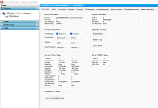
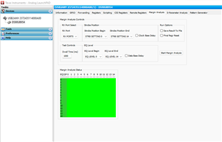
I am running the MAP tool on a 913/954 fpd link and see that all EQ and SP positions are being marked as passed. I assume this should not be the case and something is wrong as the FPD-link cable is ~5m and I would expect some positions to fail. I have attached the info page and MAP tab to see if something is wrong.

Kind Regards

Info TabMap Tab

  • Hello Mathieu,

    Unfortunately, I can't see your screen shots, can you post again please?

    What is your PCLK? and used MODE?

    Also, can you repeat the MAP test with a longer cable, between 10m to 15m? 

  • infotab

    Hope you can see this one

    I shall also test with a longer cable and let you know if anything changes

  • Here is the MAP tool screenshot

  • Hello Mathieu,

    Looking at the ALP tab it looks like this is really low frequency for the 913A/954 pair in terms of the link rate. Also the used cable is only 5m long. So it is not unexpected to get a MAP result with no errors. That basically means your system has a large margin.

    Also you are using 24MHz as a PCLK which is below our minimum specs!

  • Hi Hamzeh,

    I believe the Ref Clk is 24MHz which is inline with the specs, do you mean the pclk is 49MHz which is out of spec?

    If this is the case when I read the register setting I see the FPD3_Mode for Port 0 is RAW12 Mode/75MHz, why does ALP show a linked clock of 49MHz. I have attached a register dump as well if it is of any help.

    Thanks,


    Register Display - ALP Nano 1 - DS90UB954, Connector 1
    
    Register	Data	Name
    0x0000	0x6C	I2C Device ID
    0x0001	0x20	Reset
    0x0002	0x1E	General Configuration
    0x0003	0x20	Revision/Mask ID
    0x0004	0xDF	DEVICE_STS
    0x0005	0x00	PAR_ERR_THOLD_HI
    0x0006	0x02	PAR_ERR_THOLD_LO
    0x0007	0xFE	BCC Watchdog Control
    0x0008	0x1C	I2C Control 1
    0x0009	0x10	I2C Control 2
    0x000A	0x79	SCL High Time
    0x000B	0x79	SCL Low Time
    0x000C	0x83	RX_PORT_CTL
    0x000D	0x09	IO_CTL
    0x000E	0x04	GPIO_PIN_STS
    0x000F	0x4F	GPIO_INPUT_CTL
    0x0010	0x00	GPIO0_PIN_CTL
    0x0011	0x00	GPIO1_PIN_CTL
    0x0012	0x00	GPIO2_PIN_CTL
    0x0013	0x00	GPIO3_PIN_CTL
    0x0014	0x13	GPIO4_PIN_CTL
    0x0015	0x13	GPIO5_PIN_CTL
    0x0016	0x00	GPIO6_PIN_CTL
    0x0017	0x00	Reserved
    0x0018	0x00	FS_CTL
    0x0019	0x00	FS_HIGH_TIME_1
    0x001A	0x00	FS_HIGH_TIME_0
    0x001B	0x00	FS_LOW_TIME_1
    0x001C	0x00	FS_LOW_TIME_0
    0x001D	0xFF	MAX_FRM_HI
    0x001E	0xFF	MAX_FRM_LO
    0x001F	0x02	CSI_PLL_CTL
    0x0020	0x00	FWD_CTL1
    0x0021	0x01	FWD_CTL2
    0x0022	0x00	FWD_STS
    0x0023	0x00	INTERRUPT_CTL
    0x0024	0x00	INTERRUPT_STS
    0x0025	0x00	TS_CONFIG
    0x0026	0x00	TS_CONTROL
    0x0027	0x00	TS_LINE_HI
    0x0028	0x00	TS_LINE_LO
    0x0029	0x00	TS_STATUS
    0x002A	0x00	TIMESTAMP_P0_HI
    0x002B	0x00	TIMESTAMP_P0_LO
    0x002C	0x00	TIMESTAMP_P1_HI
    0x002D	0x00	TIMESTAMP_P1_LO
    0x002E	0x00	Reserved
    0x002F	0x00	Reserved
    0x0030	0x00	Reserved
    0x0031	0x00	Reserved
    0x0032	0x00	Reserved
    0x0033	0x01	CSI_CTL
    0x0034	0x40	CSI_CTL2
    0x0035	0x01	CSI_STS
    0x0036	0x00	CSI_TX_ICR
    0x0037	0x01	CSI_TX_ISR
    0x0038	0x00	CSI_TEST_CTL
    0x0039	0x00	CSI_TEST_PATT_HI
    0x003A	0x00	CSI_TEST_PATT_LO
    0x003B	0x01	Reserved
    0x003C	0x14	Reserved
    0x003D	0x6F	Reserved
    0x003E	0x00	Reserved
    0x003F	0x40	Reserved
    0x0040	0x00	Reserved
    0x0041	0xA7	Reserved
    0x0042	0x71	AEQ_CTL1
    0x0043	0x01	AEQ_ERR_THOLD
    0x0044	0x00	Reserved
    0x0045	0x00	Reserved
    0x0046	0x00	Reserved
    0x0047	0x00	Reserved
    0x0048	0x00	Reserved
    0x0049	0x00	Reserved
    0x004A	0x00	FPD3_CAP
    0x004B	0x12	RAW_EMBED_DTYPE
    0x004C	0x01	FPD3_PORT_SEL
    0x004D	0x03	RX_PORT_STS1
    0x004E	0x04	RX_PORT_STS2
    0x004F	0x31	RX_FREQ_HIGH
    0x0050	0x80	RX_FREQ_LOW
    0x0051	0x00	SENSOR_STS_0
    0x0052	0x00	SENSOR_STS_1
    0x0053	0x00	SENSOR_STS_2
    0x0054	0x00	SENSOR_STS_3
    0x0055	0x00	RX_PAR_ERR_HI
    0x0056	0x00	RX_PAR_ERR_LO
    0x0057	0x00	BIST_ERR_COUNT
    0x0058	0x58	BCC_CONFIG
    0x0059	0x00	DATAPATH_CTL1
    0x005A	0x00	Reserved
    0x005B	0xB0	SER_ID
    0x005C	0x18	SER_ALIAS_ID
    0x005D	0x20	SlaveID[0]
    0x005E	0xD2	SlaveID[1]
    0x005F	0x18	SlaveID[2]
    0x0060	0x94	SlaveID[3]
    0x0061	0xA4	SlaveID[4]
    0x0062	0x28	SlaveID[5]
    0x0063	0x72	SlaveID[6]
    0x0064	0x00	SlaveID[7]
    0x0065	0x20	SlaveAlias[0]
    0x0066	0xC0	SlaveAlias[1]
    0x0067	0xC2	SlaveAlias[2]
    0x0068	0x94	SlaveAlias[3]
    0x0069	0xA4	SlaveAlias[4]
    0x006A	0x28	SlaveAlias[5]
    0x006B	0x72	SlaveAlias[6]
    0x006C	0x00	SlaveAlias[7]
    0x006D	0x06	PORT_CONFIG
    0x006E	0x88	BC_GPIO_CTL0
    0x006F	0x88	BC_GPIO_CTL1
    0x0070	0x2B	RAW10_ID
    0x0071	0x2C	RAW12_ID
    0x0072	0xE4	CSI_VC_MAP
    0x0073	0x03	LINE_COUNT_HI
    0x0074	0xC4	LINE_COUNT_LO
    0x0075	0x07	LINE_LEN_1
    0x0076	0x80	LINE_LEN_0
    0x0077	0xC5	FREQ_DET_CTL
    0x0078	0x00	MAILBOX_1
    0x0079	0x01	MAILBOX_2
    0x007A	0x00	CSI_RX_STS
    0x007B	0x00	CSI_ERR_COUNTER
    0x007C	0x38	PORT_CONFIG2
    0x007D	0xBB	PORT_PASS_CTL
    0x007E	0x00	SEN_INT_RISE_CTL
    0x007F	0x00	SEN_INT_FALL_CTL
    0x00A0	0x02	Reserved
    0x00A1	0x0F	Reserved
    0x00A2	0x00	Reserved
    0x00A3	0x00	Reserved
    0x00A4	0x08	Reserved
    0x00A5	0x18	REFCLK_FREQ
    0x00A7	0x00	Reserved
    0x00A8	0x00	Reserved
    0x00A9	0x00	Reserved
    0x00AA	0x00	Reserved
    0x00AB	0x00	Reserved
    0x00AC	0x00	Reserved
    0x00AD	0x00	Reserved
    0x00AE	0x00	Reserved
    0x00AF	0x00	Reserved
    0x00B0	0x1C	IND_ACC_CTL
    0x00B1	0x15	IND_ACC_ADDR
    0x00B2	0x00	IND_ACC_DATA
    0x00B3	0x08	BIST Control
    0x00B4	0x25	Reserved
    0x00B5	0x00	Reserved
    0x00B6	0x18	Reserved
    0x00B7	0x00	Reserved
    0x00B8	0xBE	MODE_IDX_STS
    0x00B9	0x33	LINK_ERROR_COUNT
    0x00BA	0x83	FPD3_ENC_CTL
    0x00BB	0x74	Reserved
    0x00BC	0x00	FV_MIN_TIME
    0x00BD	0x00	Reserved
    0x00BE	0x30	GPIO_PD_CTL
    0x00BF	0x00	Reserved
    0x00D0	0x00	PORT_DEBUG
    0x00D2	0x90	AEQ_CTL2
    0x00D3	0x01	AEQ_STATUS
    0x00D4	0x60	AEDAPTIVE EQ BYPASS
    0x00D5	0xF2	AEQ_MIN_MAX
    0x00D6	0x00	Reserved
    0x00D7	0x00	Reserved
    0x00D8	0x00	PORT_ICR_HI
    0x00D9	0x00	PORT_ICR_LO
    0x00DA	0x00	PORT_ISR_HI
    0x00DB	0x00	PORT_ISR_LO
    0x00DC	0x00	FC_GPIO_STS
    0x00DD	0x00	FC_GPIO_ICR
    0x00DE	0x00	SEN_INT_RISE_STS
    0x00DF	0x00	SEN_INT_FALL_STS
    0x00F0	0x5F	FPD3_RX_ID0
    0x00F1	0x55	FPD3_RX_ID1
    0x00F2	0x42	FPD3_RX_ID2
    0x00F3	0x39	FPD3_RX_ID3
    0x00F4	0x35	FPD3_RX_ID4
    0x00F5	0x34	FPD3_RX_ID5
    0x00F8	0x00	I2C_RX0_ID
    0x00F9	0x00	I2C_RX1_ID
    0x00FA	0x00	Reserved
    0x00FB	0x00	Reserved
    

  • Hello Mathieu,

    ohh sorrey, I looked at the wrong position. You are correct, PCLK is 49 MHz which is all fine.

  • Hi Hamzeh, I have looked into the MAP tool and it recommends disabling the image sensor when running the MAP tool. The issue I have here is that my image sensor is outputting the PCLK to the 913. So if I disable the image sensor PCLK is lost. Is there a way to make the 913 ignore the data coming from the image sensor so I can still run the MAP tool?

    Thanks, Mathieu

  • Hello Mathieu,

    unfortunately the SER can't ignore the incoming data. Hence, it is recommended to test with MAP while the SER is getting its CLK from an external oscillator MODE not using the PCLK mode

  • Thanks for the quick reply Hamzeh, so does that mean I have no way of running the MAP tool with my current design? Could I disconnect the 12 data lines with some PCB modifications and still initialise the image sensor so the Pixel Clock still travels to the 913ser but there is no data coming in? Would I also need to disconnect FPD_VSYNC and FPD_HSYNC? Cheers, Mathieu

  • Mathieu,

    You may try to disconnect the data lines as you stated with some PCB modifications, and still initialise the image sensor so the PCLK is supplied to the 913A. But I am not sure if that will success or not. No one has tested this before!

    No, you do not need the Hsync and Vsync lines.