This thread has been locked.

If you have a related question, please click the "Ask a related question" button in the top right corner. The newly created question will be automatically linked to this question.

problem output of ads1293 using raspberry pi to collect data 3 lead ECG

Other Parts Discussed in Thread: ADS1293

Hi sir, I am waiting for your response regarding my question.

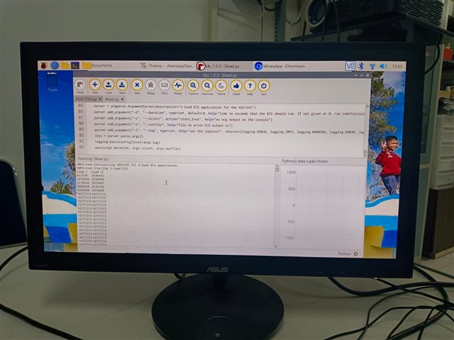
I also want to ask about the following, I once ran the program above and got the output in the form of numerical data on lead 1 and lead 2 as shown in Figures 1 and 2 below.


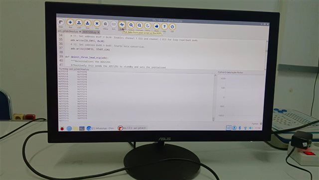
However, for the next day's experiment I did not get the numbers on lead 1 or lead 2 as shown in Figure 3 below (for this condition I did not connect the DRDYB pin to any pin on the raspberry pi).


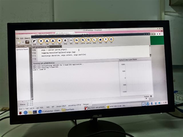
then, I connected the DRDYB pin to pin 22 on the raspberry pi and got this output in figure 4. At this output the numbers produced are the same for lead 1 and lead 2.


Thank you for your help and understanding.

  • Hi,

    Would you verbally describe/explain what your program trying to do? And, What is pin 22 on the raspberry pi and its functions?

    When the data is ready to be read from ADS1293, the drdyb voltage signal will go low, and your program needs to use that high to low signal as a trigger to ask your program to read the output data from ADS1293.

    Also, can you inject some known signal to the inputs of ADS1293? e.g. signals from ECG simulator or low amplitude(<=4mV), low frequency(<2Hz) sinusoid wave to compare the difference.

    Also, you may want to output those number you see to excel sheet or python to plot them to understand what signal or noise are you reading.

    Do you have/use an oscilloscope?