This thread has been locked.

If you have a related question, please click the "Ask a related question" button in the top right corner. The newly created question will be automatically linked to this question.

TUSB4041I: USB 2.0 Hub eHost Pre-compliance Testing

Part Number: TUSB4041I

We are currently trying to perform a high speed signal test on the USB host for our product, which is currently passing throughTUSB4041IPAPR. We realized that a USB 2.0 Test fixture recommended by USB.org and our CPU vendor (https://www.allion.com/test-fixture/hsehet/) is not suitable for generating the test packet directly.

I suspect that the hub does not support EHCI and thus we could not follow the regular procedure from USB.org. After some discussion with the support team from NXP, we were informed that we might need your help to trigger the test packet via Linux rather than using an external test fixture.

NXP provided an example from Microchip hub, and suggested to approach you for guidance on similar approach.

https://github.com/MicrochipTech/USB-Hub-Linux-Examples/tree/master/General%20USB%20Examples/USB%20High%20Speed%20Electrical%20Test

Do you have any guide to set up the USB 2.0 pre-compliance test?

  • Hello Saurabh,

    Yes, the hub will need the appropriate USB commands from the USB host to generate test packets on its downstream ports.  TI does not have any specialized instructions on how to do this, however, Linux builds do have some USB-IF protocol test capabilities and are able to send the SET FEATURE (TEST PACKET) command.

    Regards,

    JMMN

  • Hi JMMN,

    Reply from customer:

    ======

    We have been triggering the USB test packet via a software solution with sample from a different vendor :


    https://github.com/MicrochipTech/USB-Hub-Linux-Examples/tree/master/General%20USB%20Examples/USB%20High%20Speed%20Electrical%20Test


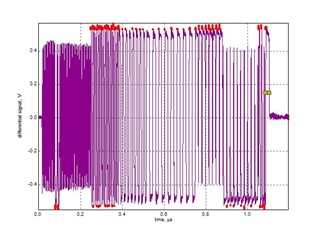
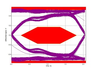
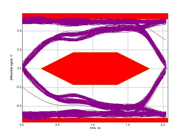
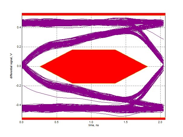
    After performing a eye diagram test on the test packet, we see that the signal is somehow different in amplitude with  TUSB4041, the test failed because the max/min voltage levels were violated, and strangely the levels are different across the pulse. What could be the reason for such a problem? I attach  part of the schematic of the hub for reference.

    In comparison, we have a similar hub from a different vendor, from a older version of our mainboard.

     USB Hub Schematic.pdf


     Your help would be much appreciated.

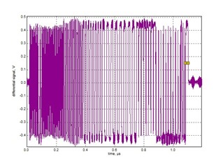
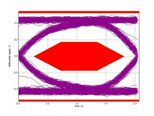
  • You can drop the transmitter strength by changing the R1 resistor from 9.53K to 10K.  Also, if you are taking near end eye diagrams, you should use the near end mask, these are far end.

    Regards,

    JMMN

  • Customer got the eye diagram test to pass for all the ports , thanks for your help.


    However, there are other tests that need your help with, for


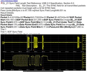
    1. Host REAR: there is a failure with the timing of the SYNC field

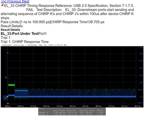
    2. Host 3, Host Front: there seems to be a failure with the CHIRP timing


    I include a PDF for your reference, which follows the naming of the schematic I sent yesterday.

     USB problem summary.pdf

    What do you think could be the cause? So far only 1 port (Host 4 passed without failure), I am not sure if it is the setup that is at fault or is there something that could be done at the circuit level?

     __________________-

     With regards to the change in precision reference resistor from 9.5k to 10k , how would the overshoot in the eye diagram test affect the functions of the USB host? We are halfway into production and are deciding whether to do a change right now.

  • Hi,

    EL_21 is not intended to be run on repeated packets, I wouldn't expect it to pass on the downstream ports of a hub.

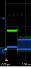
    EL_33 should pass, can you zoom in on this section so I can see the transition between Device Chirp K and the KJKJ from the hub port:

    Can you share a schematic?

    This app note explains more about the R1 resistor, but it only impacts the transmitter drive strength.

    Regards,

    JMMN

  • Schematic was attached in above thread. Are you looking for any additional information?

    This app note explains more about the R1 resistor, but it only impacts the transmitter drive strength.

    Could you share app note link?

    Will check for zoom in waveform with customer. 

  • Here's the link for the R1 app note:  https://www.ti.com/lit/an/slla429/slla429.pdf

    Sorry I missed the schematic, it looks like I actually already had reviewed it earlier.  The chirp behavior of the hub is not something that should vary from port to port or device to device.  I'm wondering if there is some kind of noise that is causing the measurement to be misread. Please zoom in on the section after the long pulse on DM (green line), that is the timing section we need to see.

    Regards,

    JMMN

  • It might be that the edge detection took the wrong edge to measure the time, and as customer change to a different cable and made multiple attempts, most of the runs were successful.

    In terms of functionality, what would a wrong transmitter drive strength do to the USB2.0 protocol? We are only concerned about the USB failing rather than pass the test.

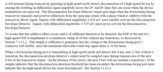
    I read in the USB2.0 Spec that this might affect the disconnect detection of the hub. Are you familiar with the implication of a stronger than necessary drive strength?

     10k


    10k

    Thanks.

  • Hi Prahlad,

    The concern with too much swing on the transmitter would be that it could trigger a false disconnect.

    From the USB 2.0 specification:

    What is the typical application, will devices be attached directly to the port or through a cable?

    Regards,

    JMMN