This thread has been locked.

If you have a related question, please click the "Ask a related question" button in the top right corner. The newly created question will be automatically linked to this question.

DS90UH949A-Q1: DS90UH949A-Q1 Schematic review / check

Part Number: DS90UH949A-Q1
Other Parts Discussed in Thread: DS90UH948-Q1

Hello Team,

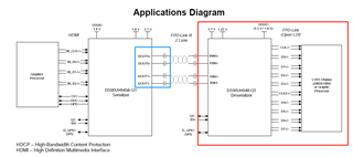
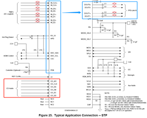
Could you please like to review my schematic of DS90UH949A-Q1(HDMI To FPD-Link III)? 

For the application of AUX Audio and I2S Audio, can you please help to give me more advice?

Moreover, is SPI 1.8V or 3.3V Level?

Thanks.

04-05--DS90UH949A-Q1.pdf

  • Hello, 

    I can do a review of the schematic and provide feedback by 5/11. 

    For audio applications, do you have any specific questions that I can help answer?

    SPI is 1.8V. 

    Best,

    Shu

  • Hi Shu,

    For audio applications, I want to know more details below.

    The definition of I2S signal from our SOC Host side: 

    I2S1_CLK --- I2S Audio Port 1 Clock

    I2S1_FS --- I2S Audio Port 1 Left/Right Clock

    I2S1_SDIN --- I2S Audio Port 1 Data In

    I2S1_SDOUT ----- I2S Audio Port 1 Data Out

    MCLK01 --- Audio Codec Master Clock

    1. For DS90UH949A-Q1, there are four Slave Mode I2S Data Inputs (I2S_DA, I2S_DB, I2S_DC, I2S_DD), just only need to use one of these four inputs, or connect all four together?

    2. For Audio Output issue, need to add the external audio circuit (same as U6 and J2 parts in the schematic) to ensure the audio normal output? Or just use HDMI TMDS and AUX signal, doesn't it need to connect to I2S?

  • Hi Hins, 

    What is the deserializer that is paired with the 949?

    The depending on the desired operation mode, only one (I2S_DA) of the data inputs need to be connected. Surround sound mode transmits all four I2S dats inputs so all four needs to be connected for that mode. 

    Can you clarify a bit more for question #2? 

    Best,

    Shu

  • Hi  Shu,

    1. DS90UH949A-Q1 is the current Serializer design part. Our clients define the Deserializer part by themselves, may be paired with DS90UH948-Q1. So we just need to confirm DS90UH949A-Q1 this Serializer's schematic, and keep DOUT0+/- and DOUT1+/- working properly for our customer's Deserializer daughterboard.

    2.  Means if only connect the HDMI input signal (like blue part), doesn't connect I2S Audio (like red part), if so, just keep display output and no audio output? If we want to keep display and audio output at the same time, we need to add the external audio circuit (same as U6 and J2 parts in the schematic) to ensure the audio normal output, right?

  • Hi Hins, 

    Thank you for the explanation. I am still working on reviewing the schematic and will be able to share feedback by the end of 5/11. 

    Since it is paired with the 948, just connecting one of the I2S data input signals (I2S_DA) is fine unless the client wishes to use all four channels for surround sound. 

    As for question #2. I believe what you are stating is correct, I will double check with the team when I get to that section on the schematic review. 

    Best,

    Shu

  • Hello, 

    I have completed the review with minor comments. Please find the attachment with feedback below. 

    04-05--DS90UH949A-Q1_Review.pdf

    Best,

    Shu