This thread has been locked.

If you have a related question, please click the "Ask a related question" button in the top right corner. The newly created question will be automatically linked to this question.

THVD8000: THVD8000 and power supply

Part Number: THVD8000

Hi team,

My customer have a question.

"o date, our products are powered by 24V DC (+/- 20%) and GND. They communicate in RS485 with the SN65HVD75DGK driver.
We could physically remove the RS 485 to pass the data over the power bus.
The THVD8000 component seems to be ideal for this, but in the documentation, we can read this: "Voltage at A or B inputs (differential or with respect to GND): –18V(min) to 18V(max)"
I think that's the problem,
How can we find a solution?"

Thank you very much for your help.

Best regards,

  • Hi Zhonghui,

    Please see RS-485 THVD8000 Design Guide here: https://www.ti.com/lit/an/slla496a/slla496a.pdf?ts=1652107823556&ref_url=https%253A%252F%252Fwww.google.com%252F

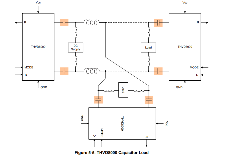
    In short - while A and B cannot be exposed to voltage outside of their ratings - the suggested setup of the THVD8000 isolates the power signal from THVD8000 through the use of capacitors and inductors - see image below:

    Using the Design equations found in the datasheet and/or design guide linked will help size the inductors capacitors - essentially the rule of thumb is that we assume that the inductors are AC grounded (this may not be technically true - but power signals will have low enough frequency that its okay for this assumption). RS-485 spec has a minimum load to Ground of 375 Ohms - so in this picture above that means the L1 and L3 are in parallel and L2 and L4 are also in parallel - at the chosen modulation frequency the impedance to ground is the parallel combination of L1 and L3 or L2 and L4 for each line - so for a mod frequency of 300KHz --> solving for total inductance in parallel Z = 2 * Pi * f * L --> L = Z/(2 * Pi * f) --> L = 375/(2 * Pi * f) = 198.944uH minimum inductance. That means if a two node system L1 and L3 would be minimum of ~400uH on each node. The capacitors just need to be < 5 Ohms for the modulation frequency and can handle the power and voltage that will be across it during operation. This is just an example as the THVD8000 can get up to 5MHz of modulation frequency allowing for smaller inductances and capacitors.  

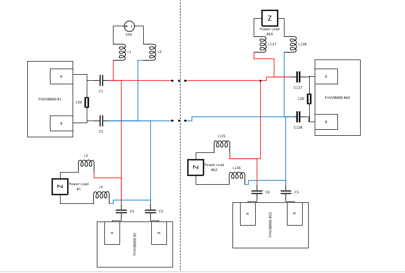
    Just as a note the device can handle multi-node systems like other RS-485 devices - please see a figure below:

    24V - 30V systems are really where this part is used the most so depending on application details this part does seem like a good candidate. There are system architectures that allow the part to go well above the 30V but it requires more than one IC and I don't think it would be necessary for this system. 

    Please let me know if there are any questions from  the customer on this information to see if they would like to learn more about the part. If your customer is trying to pass data over a power line using RS-485 type devices the THVD8000 is a great option that is used in many different system . If you have any other questions about how the part works please also let me know!

    Best,

    Parker Dodson

  • Hi Parker,

    Thank you for your detailed answer.

    I put the customer's updated questions in the attachment, please check.

    THVD8000 architecture.docx

    Best regards,

  • Hi Zhonghui,

    Thanks for the report.

    I do think there are going to be challenges with this type of implementation - it shouldn't be impossible but it will be a bit more involved. This is due to the amount of THVD8000 modules connected on the same line + distance - what is the data rate you are trying to achieve?

    The device should be rated to handle up to 256 nodes (1/8th unit load device - appx. 96K Ohm input impedance on A and B lines of device). RS-485 can handle up to 32 unit loads - with up to a max of 64 modules on the line 8 of the 32 unit loads have been used - this will impact inductor sizing on the power bus (making them larger). 

    Please see below for proposed architecture on the system (it is closer to option #2 on the diagram - but either would be okay as this is going to be more dependent on the physical layout as the extra components needed by the THVD8000 would be the same in both cases - another concern maybe that in option two the  power signal will become too attenuated with only one attachment point (I don't think this should be a huge concern but it might be something to look into). :

    So essentially in the above diagram with 64 modules - we have one power source that is fed to every other power load in parallel. The diagram assumes there is the max number of nodes (64) with the equivalent number of power loads + power sources (63 Loads with 1 Power source).

    The challenge comes in with inductance size - based on the distance you should be able to get the max of 500kbps (with 5MHz modulation frequency) as RS-485 should travel the max 80 meters with a 5MHz signal (if set up in true differential modes). 

    Assuming all nodes have power loads (they don't necessarily need to - but worst case is they do) the total impedance to ground for either the A or B line with input impedance of the THVD8000 taken into account the line to ground impedance is shown below:

    Using the smallest possible inductances (modulation frequency, fc, will be set to 5MHz) - fc = 5MHz - using the minimum input impedance of the THVD8000 (96k Ohms based on the 256 node support spec) Zin_n = 96k. If we set every inductance to be equal to each other (L_2n and L_2n-1 are always equal) it can simplify the equation. N represents the number of nodes - so in max in this use case is 64)  Using this information a general simplified formula can be found:

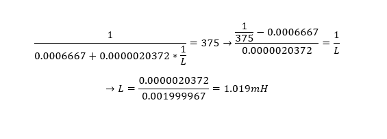
    Setting that equal to 375 and solving for L will give the minimum inductance at fc = 5MHz with 64 nodes:

    You will need 128 inductors (64 per line) at a minimum of 1.019mH of inductance each. 

    There is also the stub length to consider as well - 

    Since only device #1 and device #64 should be terminated using a 120 Ohm resistor the other 62 THVD8000's will be unterminated - however due to this the length of the stub is going to be dependent on how fast the output is transitioning. 

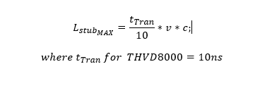
    The stub length is the length of the deviation from the main cable to an unterminated transceiver (devices #2 - #63). The maximum stub length is given by:

    Where C = the speed of light and V is the phase velocity of the signal through cable (this is usually expressed as a fraction or percentage of C - this is cable dependent). 

    This is a condition that must be met for with the design.

    Onto a few of the questions in the document you attached:

    1. Is it okay for the dc supply to be grounded ? - Yes it is okay for it to be grounded - depending on required data rate there could be a way to use this device as a pseudo differential transceiver - this means 1 wire communication. It will be data rate dependent as the differential output magnitude is cut in half in these instances but you also can cut half of the capacitors and inductors - with 80 meters of cable though this may not be possible. Also cutting to 1 wire doesn't change inductances it will be minimum of 1.019mH at 5MHz fc - modulation frequency may need to be below 5MHz with single ended setup to minimize AC attenuation of the cable - so inductance can increase.

    2. Shielded cabling? - Yes using shielded cabling is okay - we still recommend transmission lines to have 120 Ohm characteristic impedance to help mitigate reflections back onto the bus or creating standing waves. The metal bar in your implementation may be okay depending on its characteristic impedance and how much of the bus it takes up (in terms of length) - as I 'd imagine it will be some sort of discontinuity in the transmission line impedance - but if it is short enough it may not be that big of a deal. If that metal bar is behind the inductors (i.e. on the power load or power source side) it really doesn't matter that much. Strongly recommend there is a decent amount of filtering capacitance on the power loads/power sources to improve the performance of the system.  

    Some final notes:

    1. If not all 64 nodes have a power load/power source that is okay  and it could reduce the minimum inductance per node. What is shown above is worst case.

    2. Cabling is important and having a transmission line with a characteristic impedance of 120 Ohms and termination resistors of 120 Ohms on both extreme sides of the bus (device 1 and 64)  will help protect the signal integrity of the comms signal. 

    3. With the power source grounded it is possible to look into single wire power line communication depending on data rate to reduce number of passives required for the system. However this will decrease distance

    4. If max stub lengths or transmission line characteristics are not followed the chances of signal integrity issues and/or comm failures are more likely t to occur.

    If you have any other questions please let me know!

    Best,

    Parker Dodson

  • Hi Parker,

    Thank you for your help.

    The explanation was too detailed. Thanks again.

    Best regards,