This thread has been locked.

If you have a related question, please click the "Ask a related question" button in the top right corner. The newly created question will be automatically linked to this question.

SN65DSI86-Q1: SN65DSI86-Q1 SCL pin short to GND

Part Number: SN65DSI86-Q1
Other Parts Discussed in Thread: SN65DSI86

Hi TI engineers,

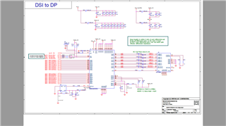
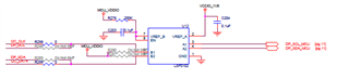
I have encountered one issue during using SN65DSI86. I found that the I2C bus of DSI86 was broken. The SCL is always driven to GND by DSI86 which will block I2C bus to send any command. I even can't send out command to the good devices hooked together with DSI86. Only after removing DSI86, I can send out I2C command. So in which case will the DSI86 SCL pin be short to GND? 

thanks and best regards,

chaodong 

  • Chaodong

    Can you please share your schematic and are you seeing this issue on multiple DSI86?

    The SN65DSI86 local I2C interface is enabled when EN is input high. Is EN input high?

    Thanks

    David

  • Hi David,

    Actually, we don't connect multiple DSI86. But we connected other IIC devices together with DSI86. The schematic is as below. Our master IIC device is 3.3V IO level. So we used one level shifter between DSI86 and IIC master device. The level shifter is as below. Unfortunately, we accidentally reverse the connection of IIC connector ( SCL connect to GND and GND connect SCL). After that, we found SCL of DSI86 was short to GND forever. 

    thanks and best regards,

    chaodong 

  • Chaodong

    Can you replace the DSI86 and see if the problem is fixed? Or do you have second board with the right I2C connection and see there is an issue with the SCL?

    Thanks

    David

  • Hi David,

    Yes, that is what we are going to do next. We are purchasing the DSI86 from vendor now. Do you think reverse pin connection will damage DSI86 completely? 

    thanks and best regards,

    chaodong

  • Chadodong

    You may need to submit the unit for FA to see if the SCL pin is getting damaged. Can you work with our local office to submit the unit for FA?

    Thanks

    David

  • Hi David,

    The damaged part was in US, CA, Santa Clara, our headquarter. Do you have office in Santa Clara? Or we can ship the part to your office?

    thanks and best regards,

    chaodong

  • Chaodong

    Please follow our customer return process here: https://www.ti.com/support-quality/additional-information/customer-returns.html, and let me know if you have any questions.

    Thanks

    David

  • Hi David,

    Got it. Will follow it.

    thanks and best regards,

    chaodong

  • Hi David,

    I have encountered another problem. I found that when I configured DSI86 into single DPHY with single lane mode, the register 0xf1 always showed 0x0b. But if I configured DSI86 into single DPHY with two lanes, it would work normally. Is there any special setting when it work in single lane mode? The register setting I used to configured DSI86 was as below.

    single DPHY with single lane

    plainI2CWriteVal.exe AQT6D0541 0x2c 0xff 0x07
    plainI2CWriteVal.exe AQT6D0541 0x2c 0x16 0x01
    plainI2CWriteVal.exe AQT6D0541 0x2c 0xff 0x00
    plainI2CWriteVal.exe AQT6D0541 0x2c 0x0a 0x06
    plainI2CWriteVal.exe AQT6D0541 0x2c 0x10 0x3e
    plainI2CWriteVal.exe AQT6D0541 0x2c 0x94 0x80
    plainI2CWriteVal.exe AQT6D0541 0x2c 0x0d 0x01
    plainI2CWriteVal.exe AQT6D0541 0x2c 0x5a 0x04
    plainI2CWriteVal.exe AQT6D0541 0x2c 0x93 0x34
    plainI2CWriteVal.exe AQT6D0541 0x2c 0x96 0x0a
    plainI2CWriteVal.exe AQT6D0541 0x2c 0x20 0x80
    plainI2CWriteVal.exe AQT6D0541 0x2c 0x21 0x07
    plainI2CWriteVal.exe AQT6D0541 0x2c 0x24 0x38
    plainI2CWriteVal.exe AQT6D0541 0x2c 0x25 0x04
    plainI2CWriteVal.exe AQT6D0541 0x2c 0x2c 0x28
    plainI2CWriteVal.exe AQT6D0541 0x2c 0x2d 0x00
    plainI2CWriteVal.exe AQT6D0541 0x2c 0x30 0x05
    plainI2CWriteVal.exe AQT6D0541 0x2c 0x31 0x00
    plainI2CWriteVal.exe AQT6D0541 0x2c 0x34 0x10
    plainI2CWriteVal.exe AQT6D0541 0x2c 0x36 0x17
    plainI2CWriteVal.exe AQT6D0541 0x2c 0x38 0x18
    plainI2CWriteVal.exe AQT6D0541 0x2c 0x3a 0x03
    plainI2CWriteVal.exe AQT6D0541 0x2c 0x5b 0x00
    plainI2CWriteVal.exe AQT6D0541 0x2c 0x3c 0x00
    plainI2CWriteVal.exe AQT6D0541 0x2c 0x5a 0x0c
    plainI2CWriteVal.exe AQT6D0541 0x2c 0x09 0x01

    single DPHY with two lanes

    plainI2CWriteVal.exe AQT6D0541 0x2c 0xff 0x07
    plainI2CWriteVal.exe AQT6D0541 0x2c 0x16 0x01
    plainI2CWriteVal.exe AQT6D0541 0x2c 0xff 0x00
    plainI2CWriteVal.exe AQT6D0541 0x2c 0x0a 0x06
    plainI2CWriteVal.exe AQT6D0541 0x2c 0x10 0x36
    plainI2CWriteVal.exe AQT6D0541 0x2c 0x94 0x80
    plainI2CWriteVal.exe AQT6D0541 0x2c 0x0d 0x01
    plainI2CWriteVal.exe AQT6D0541 0x2c 0x5a 0x04
    plainI2CWriteVal.exe AQT6D0541 0x2c 0x93 0x34
    plainI2CWriteVal.exe AQT6D0541 0x2c 0x96 0x0a
    plainI2CWriteVal.exe AQT6D0541 0x2c 0x20 0x80
    plainI2CWriteVal.exe AQT6D0541 0x2c 0x21 0x07
    plainI2CWriteVal.exe AQT6D0541 0x2c 0x24 0x38
    plainI2CWriteVal.exe AQT6D0541 0x2c 0x25 0x04
    plainI2CWriteVal.exe AQT6D0541 0x2c 0x2c 0x28
    plainI2CWriteVal.exe AQT6D0541 0x2c 0x2d 0x00
    plainI2CWriteVal.exe AQT6D0541 0x2c 0x30 0x05
    plainI2CWriteVal.exe AQT6D0541 0x2c 0x31 0x00
    plainI2CWriteVal.exe AQT6D0541 0x2c 0x34 0x10
    plainI2CWriteVal.exe AQT6D0541 0x2c 0x36 0x17
    plainI2CWriteVal.exe AQT6D0541 0x2c 0x38 0x18
    plainI2CWriteVal.exe AQT6D0541 0x2c 0x3a 0x03
    plainI2CWriteVal.exe AQT6D0541 0x2c 0x5b 0x00
    plainI2CWriteVal.exe AQT6D0541 0x2c 0x3c 0x00
    plainI2CWriteVal.exe AQT6D0541 0x2c 0x5a 0x0c
    plainI2CWriteVal.exe AQT6D0541 0x2c 0x09 0x01

    thanks and best regards,

    chaodong

  • Chaodong

    What is the pixel clock and bpp you are trying to support?

    The stream rate = pixel clock x bpp

    And DSI CLK = stream rate / (2 x DSI Lanes)

    So if you change the DSI lanes from 2 lanes to 1 lane, did you also change the DSI CLK frequency? Also keep in mind that with higher DSI CLK frequency, the setup and hold timing requirement will be tighter on the DSI lanes.

    Thanks

    David

  • Hi David,

    The parameter of my panel is as below:

    HACT=1920, HPW=40, HFP=24, HBP=16

    VACT=1080, VPW=5, VFP=3, VBP=23

    I used 24bpp @ 20fps video stream to drive my panel. 

    For setup and hold timing requirement, I think it should be ok. Because I configure both 1 lane and 2 lane mode at same speed (DSI CLK at 600MHz). 

    But only two lane mode can drive the panel while 1 lane mode always cause errors. 

    thanks and best regards,

    chaodong

  • Chaodong

    Pixel clk = Htotal x Vtotal x fps = 2000 x 1111 x 20 = 44.44MHz

    Stream rate = 44.44 x 24 = 1.06656Gbps

    DSI CLK = Stream rate / (2 x DSI Lanes) = 1.06656 / (2 x 2) = 266.64MHz,

    So why are you running the DSI CLK at 600MHz?

    Thanks

    David

  • Hi David,

    If I want to run in 1 lane mode, the speed need to be about 1.2G. To verify 1.2G speed can work, I also configure two lane mode in 1.2G speed. If two lane mode can work in 1.2G speed, there should no setup and hold timing issue for DSI86 DPHY receiver.

    thanks and best regards,

    chaodong 

  • Chaodong

    For 1 lane, since DSI data is clocked on both edge of the clock, the DSI CLK frequency will be 533.28MHz.

    For 2 lanes, the DSI CLK frequency will be 266.64MHz.

    For 1 lane, if the DSI CLK frequency is changed to 533.28MHz, are you still see error at the status register 0xF1? Also, did you clear status register 0xF1 first before reading the status register?

    Thanks

    David

  • Hi David,

    Yes, the nominal DSI clock frequency should be 533.28MHz. But the transmitter need some extra time for transition between LP and HS. So I configured DSI clock at 600MHz. And for two lanes mode, I still kept DSI clock at 600MHz so the transmitter will have longer time in LP than 1 lane mode.

    thanks and best regards,

    chaodong

  • Chaodong

    What is the value of register 0x12 when you read it for the 1 lane and the 2 lane mode?

    Also, have you cleared the status register 0xF1 and then read it to make sure the error being reported is the real error? 

    Addresses 0xF0 thru 0xF3 report errors associated with the DSI interface. Typically errors set in these fields indicate signal integrity issues. I would recommend verifying setup/hold meet DSI86 requirements. Also, adjustment of the RX EQ located at register offset 0x11 may help.

    Thanks

    David

  • Hi David,

    The value of 0x12 is 0x78 for one lane mode. And it is 0x77 for two lane mode. 

    I have wrote 0xff into registers from 0xf0 to 0xf8 before reading them. 

    Ok, I will go to check the setup/hold timing on DSI interface. And I will also try to adjust the value of register 0x11.

    thanks and best regards,

    chaodong