Part Number: TPS25750EVM
Other Parts Discussed in Thread: TPS25750, USB2ANY, BQ25792
Hi,
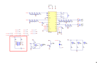
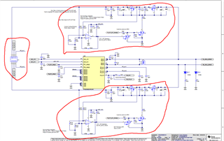
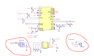
I am designing a custom board by following the TPS25750EVM reference design.
Given DATA:
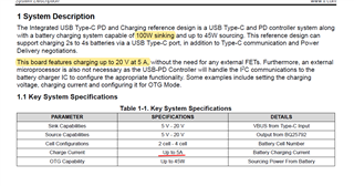
Input = 100W PD Adapter
Output = 5V/9v/15v/20v & 5A (Required)
Battery = 4S Lipo Battery 5000mAh
I have some questions to completely understand the function of each module in EVM.
- SINK = Device will receive power from USB C port to Charge BATT and provide power at SYS. Right?
- If the above question is right then I need the sink function only otherwise source.
- Do I need 5V and 3.3V Buck converter Circuits for sink application?
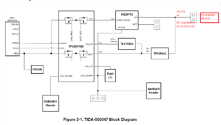
- What is Aardvark Connector?
- What is Internal Debug Connector?
- How I will interface with the web-based TPS25750 Application Customization Tool GUI?
- Do I need it to configure settings all the time after each Power shutdown?
I hope someone helps me to understand it. I have to connect the output of this EVM with the input of TPS65988EVM. The output of TPS65988EVM is connected with two devices to supply power to them.
Thanks