This thread has been locked.
If you have a related question, please click the "Ask a related question" button in the top right corner. The newly created question will be automatically linked to this question.
HI.
I designed using SN65HVD01 parts in my design.
In my design I have Chassis ground and signal ground.
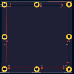
I separated the pcb layout using a capacitor and a resistor.
At this point, want to place the capacitor in each Mounting (machine) hole.
Is it a good Isolation?
(Note, it is not possible to galvanic Isolation.)
Any other recommendations?
I will wait for your reply.
Thank you
Best Regards
Hi Won,
Generally for our boards that we design we just separate the chassis ground (which we typically call Earth in our schematics) with a capacitance and resistance in parallel.
Is this board a 2 layer board? If so I think it looks okay but if you have any higher speed circuitry that runs on the other layer of the board over the gap you have shown in the picture attached it could change the impedance of the line - it probably wouldn't be a huge concern however it is something to consider especially at higher data rates/longer transmission lines - if you have four layers or more I always will suggest separating the ground planes to different layers of the board with a typical arrangement of Top Layer: Main circuit, layer 2: signal ground, layer 3: VCC, and layer 4: bottom layer (if needed for traces) + Earth. I understand it may not be possible to do more layers and if not I think what you have proposed is okay.
Please let me know if you have any other questions!
Best,
Parker Dodson
this is board a 2 layer board.
if 2 layer board are you saying that it is okay to separate the ground with multiple capacitors ( Each Mounting hole has capacitors)?
Thank you.
Parker Dodson
Hi Won,
Yes - that is correct - capacitive isolation between the planes is okay for this layout since it is layers like you mentioned. A resistor could be added in parallel to help reduce ground loop current but that is optional.
Please let me know if you have any other questions!
Best,
Parker Dodson
Hi Won,
No problem! If you have any other questions please let me know!
Best,
Parker Dodson
Hi Paker Dodson.
Thank you for replying well.
I have additional question
" resistor could be added in parallel to help reduce ground loop current" you said
Can you recommend a resistor value?
I think 0 ohms or 100 ohms are fine, but what do you think?
Thank you.
Hi Won,
Typically we see a 100 Ohm resistor between Chassis/Signal grounds when they are used. So I think 100 should be fine.
If you have any other questions please let me know!
Best,
Parker Dodson