This thread has been locked.

If you have a related question, please click the "Ask a related question" button in the top right corner. The newly created question will be automatically linked to this question.

DP83869HM: Signal Detect when in 1000-BaseX mode

Part Number: DP83869HM
Other Parts Discussed in Thread: DP83869, DP83869EVM

Hello, I'm using the DP83869HM on a custom board. I am looking on page 5 of the Datasheet:

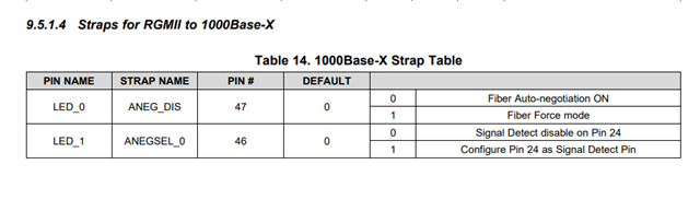
SD: In 1000Base-X and 100Base-FX mode, this pin will act as Signal Detect. This
should be connected to Signal Detect of optical transceiver.

I did not connect pin 24 to the optical transceiver, will this cause things not to work?

Joe1185.MIB_XCZU7CG_MOD 37.pdf

  • I am using the FCLF8521P2BTL Active Copper SFP which I will attached the datasheet. I believe my strapping pins are correct. When I power my board and connect the Active Copper SFP to my computer I don't see any yellow lights or green lights on the computer's ethernet jack.

    Do you see any problems?

    FINI-S-A0001269979-1(1).pdf

  • Hi joe,

    JTAG_TDI pin is required to connect to the signal detect of optical transceiver for the fiber application. Did you add the JTAG_TDI pin while you are connecting the SFP connector?

    --

    Regards,

    Hillman Lin

  • Hillman, thank you for responding to my message. I did include the schematic for your review. On the JTAG_TDI pin I only tied it to a 2.49K resistor and then to VDDIO. I could route a wire from the SFP Signal Detect pin to the JTAG_TDI pin. 

    Can you look at my schematic and comment please.

    Thank you

    Joe

  • Hi Joe,

    Schematic review will take 3-5 business day. I will provide you a comment earlier next week.

    --

    Regards,

    Hillman Lin

  • Hi Joe,

    Here is the comment I put on your schematic:

    DP8369_Schematic_Design_Review_Checklist_Interface forum_June24th.xlsx

    --

    Regards,

    Hillman Lin

  • Thank you very much

  • Hi, I have some comments:

    I don't have a external pull-up on pin 43 RESET_N, but I am adding a pull-up in the FPGA

    The 25Mhz clock on pin 20 XI the clock is a MEMS and power by 2.5V. I will see if I can lift the VDD pin on the clock and tie it to 1.8V. I don't see that on my datasheet, what page is that?

    Pin 41 MDIO has a pull-up in the FPGA.

    Joe

  • Hi Joe,

    Capacitor divider is not required for external oscillator for 2.5V. You can still keep your VDDIO to 2.5V.

    --

    Regards,

    Hillman Lin

  • Hillman, I'm trying to use the FCLF8521P2BTL which is a 1000Base-T RoHS Compliant SFP Transceiver. I attached the datasheet above. Do you see a problem using this transceiver with the DP83869HM?

    Thank you

    Joe

  • Hi Joe,

    I think this SFP connector works fine for the fiber application. I would like to double check one last time did you mean 1000BaseX?

    I have one more question on the schematic. Did you connect the LOS pin on the connector side to JTD1/TD on the PHY? Please do make sure to connect them together.

    --

    Regards,

    Hillman Lin

  • Hello, thank you for helping me. Yes, I have connected the LOS pin on the SFP connecto the pin 24 on the PHY. I did have to go through a spare pin on a voltage translator to get it int the VDDIO 1.8V domain.

    Okay, I admit I'm not an expert with Ethernet, so I'm using an SFP plug-in transfer to be able to do Ethernet communication with my computer. I did include the datasheet on the SFP plug-in transceiver. I thought the transceiver supported Gigabit Ethernet over Cat 5 cable, that would be 1000Base-T am I right. Gigabit Ethernet over copper if 1000Base-T, I thought.

    Yes, I admit now, I should not have used and SFP but used an RJ-45 connector and copper.

    Comments?

    Thank you very much,

    Joe

  • Hi Joe,

    Yes you are correct. If you are using copper connection please do you RJ45 instead if SFP connector

    --

    Regards,

    Hillman Lin

  • Hello, the board has been designed with an SFP, yes if I could go back in time I would have not used an SFP and went directly to copper, but I'm stuck with the SFP connection to the PHY.

    When I plug in my Ethernet cable to the SFP transceiver and connect the Ethernet cable to my computer I don't get any LEDs blinking on the computer's RJ45 port?

    When I run my software it never completes auto negotiation. Any ideas?

    I've set the strapping pins for RGMII to 1000-BaseX

    Led0 mode 0 for Fiber auto negotiation

    Led1 mode 1 for config pin 24 as signal detect.

    I'm stuck can you help me.

    Thank you very much,

    Joe

  • Hello, I am looking closer my the LED_0, LED_1,LED_2 strapping pins. Here is the data sheet page 47:

    Here is the Reference Design page 19

    DP83869_EVM_snlu237.pdf

    I followed the EVM example of pin strapping.

    Why is the EVM pin strapping different than the datasheet? In the datasheet Figure 31 LED_0 (Mode 1) is not represented in the EVM pin strapping. Can you comment on this?

    Last, on page 47 of the data sheet, in Figure 37, what mode is LED_1 in?

    Thank you

  • Hi Joe,

    I think I need more clarification on this. Are you trying to perform RGMII to copper DP83869 PHY? Could you give me an overview or block diagram on what are you trying to perform?

    Regarding your LED problem, we have a jumper on the EVM board which can change the strap setting from mode 1 or 0 depend on your application

    --
    Thank you

    Hillman Lin

  • Hillman,


    Hi, thank you for helping me. Yes I am going from RGMII to Copper using an Copper SFP Transceiver

    I believe my problem is the LED_0, LED_1, LED_2 strapping pins and congu

    Here is the EVM:

    Help me here please

    J2 1-2 is Mode ??

    J2 2-3 is Mode ??

    Figure 31 page 47 of the Datasheet confuses me.

    That being said, in my application do I use Table 14 on page 45 to set the correct strapping pin mode? Table 14 does not use Mode only 0 or 1. I'm confused.

    What is done with LED_2?

    Last, the data sheet and the EVM documentation don't agree on the 2-Strap Modes.

    Here is the datasheet:

    The datasheet uses Mode 0 and Mode 1

    Here is the DP83869EVM User's Guide

    The User's Guide has Mode 1 and Mode 2.

    Anyways, I really appreciate your help, truly.

    Joe

  • Hi Joe,

    In the application on RGMII to 1000Base-X mode, you only need to care about LED_0 and LED_1 strapping. LED_1 strapping always need to be in mode 1 to enable the Signal Detection for the Fiber application or connected to SFP connector so that we need J4 2-3 for the application. For LED_0, we recommend turning the auto-negotiation for the fiber application so it in mode 0 and J2 1-2 in the 869EVM.

    --

    Regards,

    Hillman Lin

  • Thank you very much. I now have a better understanding of the strapping pins. I've ordered a different SFP Copper Transceiver. Also, it could be a layout error with the PCB. 

    Thank you

    Joe