Hi,
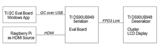
+-------------+ 4 lanes +-------------+ +-------------+ +-------------+
| MIPI0|------------>|DSI0 OUT0|------------>|IN0 LVDS0|------------>| TFT LCD |
| I2C |<----------->|I2C | FPD-Link3 | | single OLDI | 1920*720 |
| SOC | | UB941 | 2 lanes | UB948 | | |
| | | | STP | | | |
| IMX8QM | |DSI1 OUT1|------------>|IN1 | | |
+-------------+ +-------------+ +-------------+ +-------------+
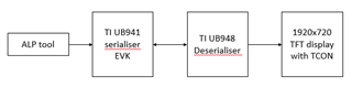
we are using ub941 serialiser and ub948 deserialiser, connections are made as shown above,
we are using single MIPI DSI and dual FPD link and single OLDI output.
could you please send the register configuration sequence that we need to do in serialiser as per the above mode and configuartion.
and the registers that we need to modify in deserialiser for single oldi.
Device tree:
&i2c0_mipi0 {
#address-cells = <1>;
#size-cells = <0>;
pinctrl-names = "default";
pinctrl-0 = <&pinctrl_mipi0_lpi2c0>;
clock-frequency = <100000>;
status = "okay";
fpdlink_serializer_i2c0: serializer@0e {
compatible = "ti,ds90ub941as_q1";
reg = <0x0e>;
reg_config = <0x01 0x08 0x1E 0x01 0x03 0x9A 0x1E 0x01 0x40 0x05 0x41 0x21 0x42 0x60 0x1E 0x01 0x5B 0x03 0x4F 0x8C 0x1E 0x01 0x40 0x04 0x41 0x05 0x42 0x0E 0x03 0x9A 0x01 0x08 0x17 0x9E 0x01 0x00>;
status = "okay";
};
fpdlink_deserializer_i2c0: deserializer@2c {
compatible = "ti,ds90ub948_q1";
reg = <0x2c>;
reg_config = <0x20 0x90 0x1F 0x09 0x1D 0x19 0x1E 0x90>;
status = "okay";
fpdlink_lvds_dic: fpdlink_bridge@100 {
compatible = "ti,fpdlink";
ti,dsi-lanes = <4>;
ti,lvds-format = <1>;
ti,lvds-bpp = <24>;
ti,width-mm = <508>;
ti,height-mm = <190>;
fpdlink-serializer-i2c-handle = <&fpdlink_serializer_i2c0>;
fpdlink-deserializer-i2c-handle = <&fpdlink_deserializer_i2c0>;
status = "okay";
display-timings {
native-mode = <&timing0>;
timing0: 1920X720_50HZ {
clock-frequency = <75193600>;
hactive = <1920>;
vactive = <720>;
hfront-porch = <40>;
vfront-porch = <31>;
hback-porch = <16>;
vback-porch = <5>;
hsync-len = <8>;
vsync-len = <2>;
};
};
port@0 {
reg = <0>;
bridge_in: endpoint {
remote-endpoint = <&mipi0_host_out>;
};
};
};
};
};
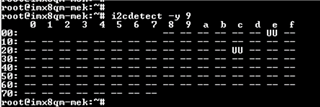
i2cdetect:
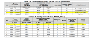
Serialiser config:
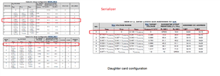
Deserialiser config:
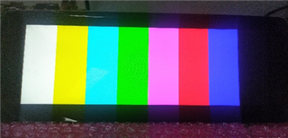
internal pattern generation is working properly,
could you please revert back on the register configuration of serialiser and deserialiser and the possible issues we are facing.
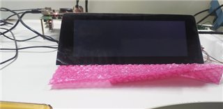
Backlight is turned on and we are getting black screen,
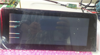
for clock frequncy 207Mhz(frequencies in the range 200Mhz-217Mh also), we are getting something as shown in below images. after doing a DSI reset using i2c commands given below.
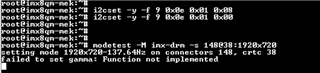
i2cset -y -f 9 0x0e 0x01 0x08
i2cset -y -f 9 0x0e 0x01 0x00
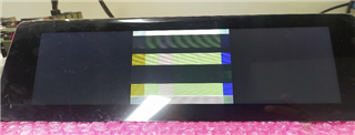
Then after running modetest command, we are getting images as shown below.
Thanks&Regards,
Musthafa av