This thread has been locked.

If you have a related question, please click the "Ask a related question" button in the top right corner. The newly created question will be automatically linked to this question.

DS90UB954-Q1: Lock loss between ser and des at high temperature

Part Number: DS90UB954-Q1

Hi team,

I am working with the DS90UB953/954 pair and I have problems with the connection cutting when the DS90UB954 works in high temperature conditions (70 degrees ambient).

The interesting thing about the situation is that when they are working and the temperature reaches 70 degrees, they work well. But, if I want them to start working at 70 degrees, they can't lock.

Regards,

Adrian.

  • Hello Adrian,

    Just to clarify, in your temperature tests, is the 954 the only device that goes under high temperature conditions, or is it the 953 and 954 together that are placed under high temperature conditions?

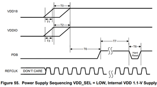
    Can you probe the power supply pins on the 954 at room temperature and then at the high temperature (70'C ambient) and check to see if the Power-Up Sequence defined in the 954 datasheet was followed in both scenarios?

    See Figure 55 and Figure 56 in the 954 datasheet and see if you can replicate the relevant figure on an oscilloscope.

    In extreme temperature conditions, additional voltage ripples may be added onto the power supply, which would affect the stability of the voltage applied at the power supply pins of the 954 device. You mentioned that the 953/954 do LOCK at normal temperature, but later lose connection when ramping up the temperature. This seems to me that the Power-Up Sequence was followed at room temperature, but as the temperature rose, the voltage ripple on the power supply pins exceeded the limit of 1.8V(+/-5%) and 1.1V(+/-5%).

    If excessive voltage ripple is present at 70'C ambient, then if you try to power-up the 954 device at 70'C the Power-Up Sequence might not have been followed and the 954 will act in an erratic behavior.

    Best,

    Justin Phan

  • Hi Justin, thanks for the quick reply.

    In a first test, I put both devices on high temperature and got this error. When analyzing the cause, I understood that the problem was the 954 and so I am putting only this one at high temperature.

    About the power up sequence, I think it is not related to my problem, because I am not turning the system off and on.

    At high temperature, I can't see video image coming through the 954. When I run the script that allows me to see the image, at high temperature, I have no response.

  • Hello Adrian,

    1. When the 954 is the only device placed in a high temperature environment, are you still able to properly send I2C commands to the 954 device from your processor or lab computer?
    2. When the video image is failing to be outputted by the 954, can you read register 0x4D in the 954 multiple times, to check if there is still a stable LOCK between the connected 953 and 954 devices?
      1. Below is the general sequence of I2C commands that I would like for you to perform. 
      2. WriteI2C(DES, 0x4C, 0x01)
        ReadI2C(DES, 0x4D)  
        time.sleep(0.1) / Some delay between each read
        ReadI2C(DES, 0x4D)
        time.sleep(0.1)
        ReadI2C(DES, 0x4D)
        time.sleep(0.1)
        ReadI2C(DES, 0x4D)
      3. After multiple reads to register 0x4D, the LOCK_STS bit should remain at 1 and the LOCK_STS_CHG bit should remain at 0, to indicate stable LOCK.

    Best,

    Justin Phan 

  • Justin,

    If I'm late in answering, it's because I'm doing the tests.

    It is happening to me that I can read the registers of the 954 up to a temperature of approximately 58 degrees. Exceeding that temperature, I cannot read the registers, but I can see a video image.

    When I get to 70 degrees, I can't do or see anything.

    It's very strange.

  • Justin,

    We are using the internal 1.1V linear regulator in the 954.

    In addition to this, we measure that the i2c data signal when it is about to stop working, drops from 1.8 to 1.1v approximately.

  • Hello Adrian,

    It still seems to me that some voltage rail on your 954 board is failing when temperatures reach about 58'C and approaches 70'C. If you can't send I2C reads to the 954 at around 58'C, then either the I2C pull-up voltage has become unstable at this temperature or the power supply rails to the 954 chip have exceeded the voltage ripple limits.

    I recommend placing oscilloscope probes in the temperature chamber along with the 954 board and trying to record the voltage being applied to the power supply pins of the 954 device. See if you can replicate the Power-Up Sequence defined in the 954 datasheet:

    It may also be a good idea to measure the I2C lines in the high-temperature condition and see what the results look like on an oscilloscope as well.

    In addition, if you are measuring the I2C data line on the 954 board and are measuring 1.1V instead of the expected 1.8V, then that also seems to indicate some issue with the voltage rails being used in the board.

    Can you confirm if you are measuring the I2C data signal with a multimeter or an oscilloscope?

    If measuring DC voltage with a multimeter, then the multimeter will output the average of its reading. If the I2C data line is very noisy, then a multimeter will average the readings as a single DC voltage value, which might explain why the reading is 1.1V instead of the expected 1.8V. 

    If you are measuring from an oscilloscope, could you post any relevant oscilloscope screenshots in the E2E forum as well, so that I can review?

    Best,

    Justin Phan 

  • Hi Justin,

    I am doing all the measurements with an oscilloscope.

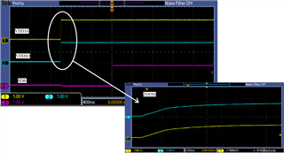
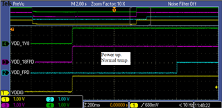
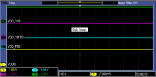
    The following image shows the power-up sequence. It is not altered by temperature.

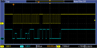
    Also, we measure the I2C signal that is altered when there is a temperature increase. I show a photo below.

    Regards,

    Adrián.

  • Hello Adrian,

    Thank you for the screenshots and the additional clarification on the issue in your system. 

    1. How many units of the 954 board has this issue occurred in, out of all of the boards produced?
      1. Knowing this would help me narrow down if this is a systemic issue or with individual components on isolated boards.
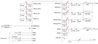
    2. Would you be able to provide the schematic of the 954 board, so that I can look around for anything that might be a possible cause?
      1. This is a public forum, so you may also send a private message with more details instead of posting here.

    Best,

    Justin Phan

  • Hello Adrian,

    1. I have received your schematic, but some connections are not shown, such as what components are on the SCL/SDA pins and what connections are made on the REFCLK pin.
      1. Can you clarify if there are any other components on the I2C bus, besides the pull-up resistors?
      2. Can you also verify that all of the components on the 954 PCB board are rated to operate at automotive temperatures of at least +105'C (including the capacitors, buck converters, oscillator, etc...)?
    2. Can you also probe all of the power supply pins on the 954 at 70'C ambient temperature, to see if there is any voltage instability after the device has successfully powered-up?
      1. The previous screenshot shows the Power-Up sequence, but I would like to see if the voltage being inputted into the 954 device becomes unstable at any point after temperatures reach 70'C.

    Best,

    Justin Phan

  • Hi Justin,


    The SCL/SDA and REFCLK pins are controlled by an NVidia module, running a Linux operating system. I measured the REFCLK at normal temperature and at high temperature, and it has no change.


    Also, I measured the input voltages to the 954 at low and high temperature, and they are stable.


    The components on the 954 PCB board, I'm not sure if all of them can work up to 105 degrees. Yes, they can do it up to 85 degrees and some up to 125 degrees. Anyway, we have the problem at 70 degrees.

    Regards.

  • Hello Adrian,

    Can you investigate if this is an issue that is related to the thermal relief vias underneath the 954 chip?

    We have a recommended Land Pattern in the 954 datasheet, which shows multiple ground vias underneath the DAP for thermal relief and for the ground connection between the 954 chip and the PCB. If there are not enough thermal vias or issues with soldering, then the 954 chip may not properly dissipate heat during normal operation and can overheat at lower ambient temperatures.

    Here is also an App Note that goes in more detail:

    https://www.ti.com/lit/an/slua271b/slua271b.pdf?ts=1649202546074&ref_url=https%253A%252F%252Fwww.ti.com%252Fsupport-packaging%252FSMT-application-notes.html 

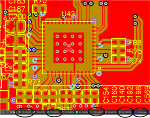
    Would it be possible to provide a picture of the DAP used for the 954 in the PCB and the layout files offline, for me to review?

    And getting back to a previous question, you mentioned that all 954 boards that were developed experienced failure. How many 954 boards were built?

    Best,

    Justin Phan

  • Another question, are there any other components on the I2C bus, besides the 954 chip and the NVIDIA module, which may influence the I2C bus?

  • Justin,

    We have considered the thermal relief and we have GND vias under the central PAD to dissipate the temperature. These are connected to different GND and bottom planes on the board.

    This problem happened to us on all 20 boards built with the 954.

    On the I2C bus, between the 954 and the NVidia module we have an FPGA. But according to the previous photo of the I2C signals, as the CLK signal that is handled by the master (NVidia) is correct, and the data signal that can be handled by both (Nvidia and 954) is failing, we suspect that the problem originates from 954.

    What do you think?

  • Hello Adrian,

    This is a tough issue. Since all 20 boards that you have built have the same issue, then this is likely some systemic issue and not a chip-level issue. Normally, issues due to extreme temperature are because of instability being introduced into the voltage rails that are being supplied to the FPD-Link device.

    If not that, then I would suspect that this is a soldering issue. Maybe there was an issue with how the 954 chips were soldered onto the DAP on the PCB board and the solder paste is coming loose at higher temperatures?

    Will it be possible for you to research into local professional PCB rework services and have them remove the 954 chips and then cleanly reinstall them onto the PCB board again? 

    The QFN and SON PCB Attachment App Note that I shared previously includes our guidelines on solder paste for QFN packages.

    Would it also be a possible option to send a faulty system to our Santa Clara, CA office in the United States, so that we can have a system on hand for debug? I am unfamiliar with a company named Plantium, so I am not sure if this is a feasible option.

    Best,

    Justin Phan

  • Hi Justin,

    Sorry for the delay in replying to you, but we were running several series of tests according to your recommendations.

    The problem was in the soldering of the central PAD to the PCB. With a rework on the chips, we get them to work correctly.

    Thank you very much for your help.

    Adrian.