This thread has been locked.

If you have a related question, please click the "Ask a related question" button in the top right corner. The newly created question will be automatically linked to this question.

TCAN337: TCAN337 IC Failure and burned out

Part Number: TCAN337

HI,

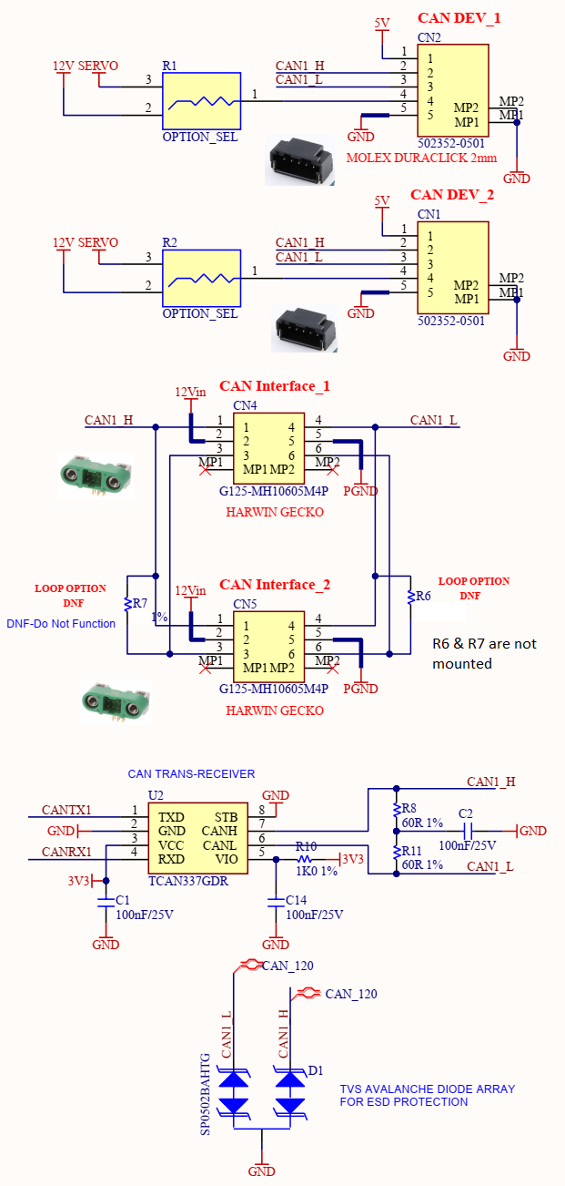
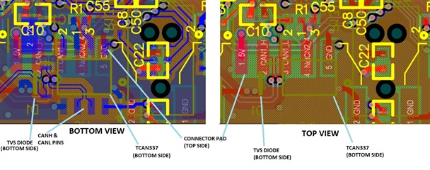
I am using TCAN337 to connect upto 7 CAN nodes in a network for automotive application. I have dual CAN configuration, where CAN1 has 5 nodes and CAN 2 has 4 nodes. The circuit includes split termination (two 60 Ohms along with 0.1uF capacitor to ground) on one end (inside PCB) and standard termination with 120 Ohm physical resistor at connector of the last node. We also have SP0502 TVS protection diodes (rated at 5.5V and clamping at 8.5V) between CANH to ground and CANL to ground for each nodes (PCBs).

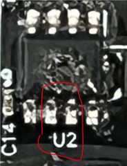
Recently we have observed failures in our CAN2 network. Two TCAN337 IC of our CAN-2 network were damaged. Out of them one TCAN337 IC has literally burned out and burn mark is visible with naked eye. We also found that TVS diode on CANH of this IC has failed in open mode. The other TCAN337IC is not burnt and TVS Diodes are also intact, but it does not do any communication. 

Also it is important to note that the system was fully functional during the last testing two days ago and after that when we tried to power up this system today, then we observed these failures.

We have noticed two such occurrences of failure of TCAN337 and TVS Diode SP0502 for same node locations but in different setup.

Kindly guide me where we are doing wrong? What could have caused such a excessive burn out of TCAN337?

Is 5.5V TVS diode OK for a CAN network having TCAN337 trans-receiver operating at 3.3V?

All you valuable suggestions, insights and feedback on this are welcome. 

Thanks. 


  • Hi Jit,

    Can you send over a schematic of the CAN transceiver that burned out. It is possible there was a fault event that caused an excessive amount of current to run through the device and that could cause the device to internally burn. However, this device has a bus fault protection of up to +/- 14V. Is it possible that a high voltage line was running close to CANH and CANL bus? Could a high voltage line been accidentally connected to the CAN bus?

    Once I see the schematic we can make a better judgement on what might have happened.

    Best,

    Chris

  • Dear Chris,

    Thanks for your reply. I am attaching the CAN section of our CAN Boards.

    There are several such boards and each board serves as one CAN node.

    Each card has two CAN connectors (CN4 & CN5) out of which one is for input CAN connector and second is for output CAN connection.

    Each connector for CAN has got 6 wires - One for 12V supply, One for Ground, One of CANH, One for CANL, One for CANH-LOOPBACK and one for CANL-LOOPBACK. The CAN connection running into this board enters through CANH and CANL. Then it is looped back to the next CAN board using a CANH-LOOPBACK and CANL-LOOPBACK. This way we can daisy-chain all the nodes in our CAN network. The last board does not use the LOOPBACK connection but instead uses a 120Ohms termination resistor. The resistors R8 and R11 are not mounted on CAN boards except for the first controller board which has a microcontroller controlling the entire system operations. There is a shield above these 6 wires, but the shield is left unterminated on both ends. Also this bunch of 6 wires run close to 48V live and return wires running from battery to the motors. The connectors CN1 and CN2 are mounted on boards and are for debugging purposes only and do not have any harness in actual operation. 

    Kindly let me know if you need further details. Thank you for your support and valuable guidance.


  • Hi Jit,

    I'll look through this information and get back to you tomorrow.

    Best,

    Chris

  • Hi Jit,

    Have you double checked to the wiring and connectors to make sure that they are connected correctly. You might be shorting the 12 V rail to GND on the device that burned.

    I would start off by checking all your psychical connections. Also can you send me a picture of the device that got burned? If possible are you able to tell which pin got damaged?

    My only question about the schematic is the VIO pin. The TCAN337 does not have a VIO pin. Pin 5 is a FAULT pin. Can you confirm which device you are using?

    Best,

    Chris

  • Hi Chris,

    Thank you for your reply. Yes we have double checked that there is no shorting between 12V rail to GND as our wiring is fixed and our connectors can't be mated in opposite direction. 

    We have measured the impedances of all pins of the faulty TCAN337. Here is a summary of our impedance measurements.

    Impedance                --------System-1----------------             ---------System-2------------      Good Device

                                      Burnt IC-1          Failed IC-1             Burnt IC-2      Failed IC-2

    CANL to GND           2.3M                   83K                        28K                70K                  2.3M

    CANH to GND          2.3M                   27K                        42K                1.3K                 2.3M

    CANH to CANL         56K                    46K                        70K                 42K                 56K

    VCC to GND             32 Ohms            1.9K                       25 Ohms         32K                 233K

    RX to GND               4.4 Ohms            OPEN                    80 Ohms         OPEN             OPEN

    The VIO pin is actually a pull up for the Fault pin and it is just named as VIO and not used. 

    I am sharing the photos of burnt IC for your reference.

    Regards,

    Jit

  • Jit,

    Are these two pins the VCC and GND pins?

    Did you also take a measurement of TX to ground? I'm sorry if you said this before but what is the difference between the burnt IC and the failed IC? Are they on the same board and located near each other? It looks like the VCC rail suffered a strong short to GND. Are all your CAN transceivers on the same board or do they have their own induvial boards that connect to each other.

    I think the next step here would be to double check the design files. If you are comfortable sharing the project with me let me know.

    Best,

    Chris

  • Dear Chris,

    Thank you for your prompt reply. 

    The two pins are not VCC and GND but are CANH and CANL pins.

    I have took the measurement of TX to gnd but all are showing open for good and bad ICs and hence did not mention it here.

    We had failures in two separate systems. In both failures, two CAN boards have failed. In each system, one CAN board has got a severely damaged (burnt) TCAN337 IC and a second TCAN337 IC which is not burnt or damaged externally but is not working. 

    TCAN337 ICs are located on different boards and boards are connected through the CAN wiring connectors (CN4 and CN5 shown above).

    In summary we have a system of two CAN buses CAN1 and CAN2. CAN-1 has 5 separate boards each having one TCAN337 IC. CAN-2 has 4 separate boards each having one TCAN337 IC. We have observed that two TCAN337 ICs in two boards of CAN-2 have failed, where one is literally burnt out and second is visually OK but not functional. We have had two such failure observations in two systems (Totally 4 TCAN ICs have failed (2 burnt and 2 faulty)).

    Hope that this clarifies the system.

    Regarding sharing of project I will have to check with my system admins. Meanwhile do let me know if you can have any clues regarding this failures.

    Thanks and regards,

    Jit 

  • Jit,

    Do all the boards share the same PCB design? If you populate a different IC onto the board that burned the last one does the same board burn the new IC?

    I am going to check with design to see if I can find out what part of die is located under that melted mark. Let me know if you can share the PCB design.

    Best,

    Chris

  • Dear Chris,

    Sorry for the late reply.

    All boards share the same PCB design. Also I checked if there is any component on bottom side of transreceiver but there is nothing exactly below CANH & CANL lines. There is a partial area cover by the connector on the top side which has a 12V net (NETCN2_4). (See figure)

    Yes we replaced the CAN transreceiver and TVS diode in cards with Burnt IC as well as Faulty IC. We found that the cards which had faulty ICs are now up and working fine. But the cards which had burnt IC have now normal currents, but the CAN node still can't be detected after IC replacement. We probed the CANH/CANL lines to see the behaviour and found that in absence of any CAN node the CANH and CANL waveforms of the Card (having the burnt IC replaced with a new one) are OK (complimentary data patterns visible on scope), but the moment we connect it to another good CAN node, the CANH/CANL waveforms are no longer normal (infact we see same polarity swings in CANH and CANL). Still trying to understand this behaviour.

    Regarding full PCB, we can share to you directly in case you are willing for an NDA. 

    Thanks for your support and do let me know if you can figure out anything.

  • Jit,

    In both cases, it seems like electrical overstress is occurring. The burnt out IC is obvious because it catastrophic damage caused by heat aka excessive power. The burnt ICs show a low impedance short on VCC to GND, which would indicate damage along that path, and the failed ICs show a low impedance short on CANH and CANL, which is typically of overvoltage damage on the CAN bus. Also the fact that the TVS diode is burnt out is just more evidence that electrical overstress has occurred.

    Can any waveforms be captured of the system? I know it's difficult to capture random damage occurring, but all the information we can get will be helpful.

    Regards,

    Eric Hackett 

  • Dear Chris and Eric,

    Thank you for your support. Your recommendations were pointing out to a overstress occurring in the system. But it took us some time to locate the source of the overstress. After several investigations, we found that in our system we were using a loopback connector. Occasionally we were using a temporary loopback connector which was not properly soldered/sleeved and so we suspect that due to this connector there might be a temporary shorting between CANH and 12V supply since the pins were adjacent in our connector. We tried to simulate the failure on some cards by shorting CANH to 12V and we found that in presence of TVS diode, the TVS diode first fails in short mode and after that becomes open. In such cases the TCACN337 fails but does not burn out. However if the TVS diode is absent and if there is a shorting then it leads to burn out of TCAN IC similar to what we had seen.

    The exact failure mechanism is still not clearly understood, but our hypothesis is that most likely there was a shorting between CANH and 12V. If shorting is momentary then only TVS diode fails (first in short mode and then in open mode), but if it is sustained then TCAN also fails. In case of TVS diode becoming open due to momentary shorting, any further fresh shorting, leads to a burn-out of TCAN. Please share your thoughts about it.