This thread has been locked.

If you have a related question, please click the "Ask a related question" button in the top right corner. The newly created question will be automatically linked to this question.

DS90UB948-Q1: pattern generation

Part Number: DS90UB948-Q1
Other Parts Discussed in Thread: ALP, USB2ANY

Dear expert,

In UB948 datasheet,  CML_OUTPUT_CTL3 register "CML TX must be powered down prior to enabling Pattern Generator."

Why there is this requirement? My customer never do this but Pattern Generator is still OK.

In 7.3.16 Internal Pattern Generation, "Enabling PATGEN on the DS90UB948-Q1, using the internal clock, will cause loss of communication between the serializer and deserializer, so internal PATGEN from the DS90UB948-Q1 should only be enabled via local I2C access."

What does this mean? 

One of my customer A use UB941 to configure UB948 pattern. Pattern works fine and LOCK is stable during pattern.

My another customer B use UB941 to configure UB948 pattern, they see unlock after 0x64 bit 0 to Enable Pattern Generator and there is no output at screen.

They use the same pattern configure. The main difference is customer A has both external reference clock and DSI clock valid. Customer B 's board is new board who don't have external reference clock and DSI clock is not present. So we use internal reference clock to debug first. Does it make difference? And that's why there is no output at screen?

Thanks

  • Hi Ryan,

    In UB948 datasheet,  CML_OUTPUT_CTL3 register "CML TX must be powered down prior to enabling Pattern Generator."

    Why there is this requirement? My customer never do this but Pattern Generator is still OK.

    In 7.3.16 Internal Pattern Generation, "Enabling PATGEN on the DS90UB948-Q1, using the internal clock, will cause loss of communication between the serializer and deserializer, so internal PATGEN from the DS90UB948-Q1 should only be enabled via local I2C access."

    What does this mean? 

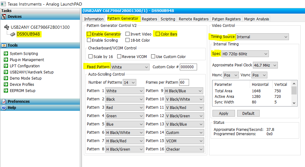
    Do not configure CML_OUTPUT_CTL3 on the 948 for 941AS PATGEN. I never had to configure any special registers to achieve internal patgen from 948 side, if you can use our ALP GUI that would make it much easier for you to enable Pattgen or any other functions. 

    My another customer B use UB941 to configure UB948 pattern, they see unlock after 0x64 bit 0 to Enable Pattern Generator and there is no output at screen.

    You do not need to configure any 948 side registers to achieve 941AS side PATGEN. Also to answer your question, when 948 is the one generating the pattern, then you will not see LOCK between the 941AS and the 948 (if the 948 is using internally generated clock). 

    They use the same pattern configure. The main difference is customer A has both external reference clock and DSI clock valid. Customer B 's board is new board who don't have external reference clock and DSI clock is not present. So we use internal reference clock to debug first. Does it make difference? And that's why there is no output at screen?

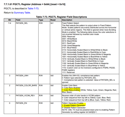
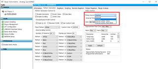
    Are you getting into the correct timing source? You need to make sure you are selecting internal mode if you are not running any external clk otherwise you won't get any video output.  as far as 0x64 bit 0 , it needs to be set to 1 to enable patgen

    example - to enable PATGEN and Select Color bars you can do the following:
    board.WriteI2C(UB948,0x64,0x05) # Color bars with patgen enabled
    board.WriteI2C(UB948,0x65,0x04) # Internal timing

    If you have Aardvark or USB2ANY, you can connect the I2C lines to the target board and then connect via USB to your PC. Then you should be able to access 941 / 948 through the ALP GUI to help check registers, configurations, PATGEN etc. quickly. Is this something you have the capability to utilize?

    Regards,
    Fadi A.