This thread has been locked.

If you have a related question, please click the "Ask a related question" button in the top right corner. The newly created question will be automatically linked to this question.

DP83867IS: Connected to 1Gbps with signal error

Part Number: DP83867IS
Other Parts Discussed in Thread: TDA4VM, , DP83867ERGZ-R-EVM

Hello TI experts,

Last time I asked about DP83867 for my customer ;

https://e2e.ti.com/support/interface-group/interface/f/interface-forum/1111199/dp83867is-cannot-go-to-link-status-after-eth0-up-under-1000mbps

They solved some problems and made 2nd PCB. but there are still problem.

when they tried to transmit video data with 100Mbps speed, it is fine.

but when they tried to connect with 1Gbps, some errors are occur. (broken video file) 

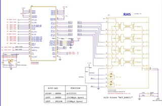
- they used LPJG16314A4NL RJ45 connector, same as TDA4VM EVM.

- when they connect RJ45 connect which is same as EVM, link does not active.

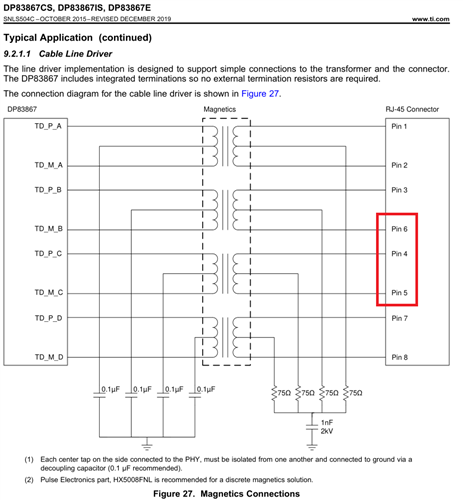
- when they connect 4pin->6pin/5pin->4pin/6pin->5pin of RJ45 connector, link is active and ping test is normal, but transmitted video data is broken.

Could you guide me about the possibilities of this error? and it would be very helpful if you teach me something to fix (schematic, layout, software, anything.)

And please let me know if you need more information about this issue. (the schematic is same as before.)

Best regards,

Chase

  • Hello Chase,

    I am not understanding what you mean by your statement in third bullet point. There shouldn't need to be any modification on RJ-45 connector as connection should be straightforward to establish link.

    Under normal conditions, if 1G speed is required, auto-negotiation must be enabled for 1G communication for both sides; no forcing. Is only 1G being advertised? 

    Please provide register data for registers 0x0, 0x1, 0x4, 0x5, 0x9, 0xA, 0x11.

    Also, this transformer does not look like what we have recommended in our datasheet. It appears that center taps are shorted on PHY side which violates datasheet.

    Sincerely,

    Gerome

  • Dear Gerome,

    Thank you for your support.

    Here are more information from my customer.

    1. They connected 4/5/6pin across each other because they saw typical application in the datasheet. as you can see, the sequence is little different.


    2. They enabled Auto-negotiation.

    3. Here are the register dumps.

      (1) the case when the 4/5/6pin is switched, and RJ45 connector without transformer -> it works great.

    0x0 : 0x1140
    0x1 : 0x796d
    0x4 : 0x01e1
    0x5 : 0xcde1
    0x9 : 0x0300
    0xA : 0x7800
    0x11 : 0xbc02

      (2) the case when the 4/5/6pin is switched, and RJ45 connector which is used in TDA4VM EVM (LPJG16314A4NL, LINK-PP, with transformer) -> it does not work, link is not established.

    0x0 : 0x1140
    0x1 : 0x7979
    0x4 : 0x01e1
    0x5 : 0x0000
    0x9 : 0x0300
    0xA : 0x0000
    0x11 : 0x0002

      (3) the case when the 4/5/6pin is NOT switched, and RJ45 connector which is used in TDA4VM EVM -> it is connected to only 100Mbps.

    0x0  : 0x1140
    0x1  : 0x796d
    0x4  : 0x01e1
    0x5  : 0xcde1
    0x9  : 0x0300
    0xA  : 0x0000
    0x11 : 0x7c02

    4. As I said, my customer used the same RJ45 connector which is used in TDA4VM EVM.

    what is your suggestion for transformer and RJ45 connector? and please let me know clearly about the connection of RJ45 communication line.

    (cross connection of 4/5/6 pin or not)

    5. Is not it necessary to supply any voltage to pin2 of RJ45 connector?

    6. I attach a layout of customer's PCB for your convenience.

    2352.Layout.zip

    schematic is same as before.

    Please advise me to solve this problem. Thanks.

    Best regards,

    Chase

  • Hi Chase,

    I am still not understanding what you mean by 4/5/6pin across each other. Would you be able to draw a diagram between 2 RJ-45 pinouts so I can better understand the setup?

    Sincerely,

    Gerome

  • Dear Gerome,

    Hope you had a good weekend.

    Here is simplified diagram for you.

    # Case 1 (pin 4,5,6 is directly connected to TD_M_B, TD_P_C, TD_M_C each without transformer.)

    # Case 2 (pin 4,5,6 is directly connected to TD_M_B, TD_P_C, TD_M_C each with transformer.)

    # Case 3 (pin 4,5,6 is directly connected to TD_P_C, TD_M_C, TD_M_B each with transformer -> It only works to 100Mbps.)

    1. I already confirmed that the schematic of my customer and TDA4VM EVM is the same. (just like Case3)

    Does it have any possibilities of layout between DP83867IS and RJ45 connector? (impedance mismatching or other reasons)

    2. I saw about strap configuration from 37 page of the datasheet and so on TDA4VM EVM's schematic. Is it necessary?

    3. Is it effective to add o.1uF capacitor between MAC and PHY?

    we can see 0.1uF series capacitor on SGMII line but cannot see on RGMII lines. (datasheet 25 page and 27 page)

    please answer all my questions if you can (including register dump), then we can eliminate the possibilities of fault situation and focus on other possibilities.

    Best regards,

    Chase

  • Hi Chase,

    With any configuration of our PHY, we require the MDI configuration dictated in our datasheet. Any configuration that deviates from this, whether it be lack of transformers, different style wiring, etc. puts validation responsibility solely on customer.

    I am still unsure what is the purpose of pointing out pins 4-6 on RJ-45. Where is all the other pins?

    DC blocking capacitors are needed for SGMII as this utilizes LVDS signaling. RGMII does not require DC blocking capacitors.

    Sincerely,

    Gerome

  • Dear Gerome,

    Thank you for your support.

    1. How about register dump? can you see anything strange in it?

    2. I saw that the strap configuration of TDA4VM EVM and DP83867IS EVM are different.


    (Left is in TDA4VM EVM, right is in DP83867IS EVM.)

    which one is prefer for standard operation? and should we change register settings if we use different strap configurations?

    Best regards,

    Chase

  • Hi Chase,

    With register dump, I can make some sense of it, but I am not clear on what the setup is with the RJ-45 still. What are the other pins connected to? Since customer is trying to accomplish 1G communication, all pins are needed.

    Both sides have independent configuration that is for their own use cases. It appears that the DP83867ERGZ-R-EVM does need RX_CTRL strapped to Mode 3 or 4 (looks to be using default). The only differences between the EVMs are RX_CTRL and LED_1 (TDA4 in mode 2, 867 EVM is mode 1. Both are valid configurations). Configurations are all dependent on your customer's use case.

    Sincerely,

    Gerome

  • Dear Gerome,

    Thank you for your support.

    finally they succeed to make link up and transfer video stream.

    but still they have some problems.

    - ping does not work from PC to sample board (1Gbps connection)

    - transfer speed is different from board to board. (one board is 100Mbps, another is 600Mbps.)

    Here is the register dump.

    register : 0x0, 0x1, 0x4, 0x5, 0x9, 0xA, 0x11

    value    : 0x1140, 0x796d, 0x01e1, 0xcde1, 0x0300, 0x7800, 0xbf02

    Could you give me some advice about this situation?

    Best regards,

    Chase

  • Hi Chase,

    What was done to make linkup work?

    In terms of the other issues you are facing, please utilize loopbacks on PHY to understand if there is problems originating in the MDI or MII interface. You should be able to use the MAC's packet generator and checker to see if there is issues on either front. Use loopbacks like MII loopback to isolate the MII interface, while using Reverse loopback to isolate the MDI (a LP will be needed for this). 

    Thank you for register dump. It appears that the PHY has auto-negotiated to 1G speed, so that does not appear to be the issue. Is this register values the same on both boards (100mbps board and 600mbps board)? Are there packet errors?

    Sincerely,

    Gerome