This thread has been locked.

If you have a related question, please click the "Ask a related question" button in the top right corner. The newly created question will be automatically linked to this question.

SN75DP130: Application inquiry

Part Number: SN75DP130
Other Parts Discussed in Thread: TDP142, SN65DP141

Hello Team,

My customer is using the SN75DP130 DP redriver to drive a DisplayPort output out of an FPGA. They do not want to implement a DP130 in a sink, but implement a DP130 in a source side (before the cable). My question is how the source shall deal with link trining, since the DP130 will do the link trining with the sink?

Regards,

Renan

  • Renan

    Do we know if the FPGA DisplayPort output is DisplayPort compliant or not? If the output is DisplayPort compliant, why not use SN65DP141 or TDP142? SN65DP141 or TDP142 is a linear redriver instead limited redriver. The linear redriver helps compensating the signal but does not participate in the link traning.

    Thanks

    David

  • Hello David,

    Please see the response from my customer below:

    Thanks to this topic to highlight alternatives to DP130 as linear redriver without link training. I understand the point.
    But I want to keep focus on my current implementation with DP130.
    Yes my source is DisplayPort compliant, and would be able to do link training if the sink would be connected directly to it.
    But my question is: in my case with DP compliant source doing a link training, how does it interacts with DP130 that also do a link training. Shall it be transparent, or shall I tune my source firmware to bypass some parts of the link training?

    Regards,

    Renan

  • Renan

    DP130 “snoops” the AUX channel and receives input from the link training process. In this case, it will adjust its VOD and Pre-emphasis level base on the sink request. Based upon this input, DP130 adds boost in the channel and automatically adjusts its EQ. But there is no communication between the DP source and DP130 regarding the link training information.

    Please see attached slide as I try to explain the potential pitfall when using DP130 limited redriver. In this case, they can turn off the DP source link training and manually tune the DP source VOD and Pre-emphasis level to compensate for the channel between the DP source and DP130, and let DP130 handle the link training for the channel between DP130 and the sink, or they can use a linear redriver.

    Limited_Redriver_Link_Training_Limitation.pptx

    Thanks

    David

  • Hello David,

    Please see my customers response below:

    Thanks for this information that meet my expectation.
    I now understand how the DP130 interacts, and my understanding is that snooping the AUX makes this process transparent to the source software. In my implementation, I did split the transceiver VOD/preamp reconfiguration at the source, since it is done between DP130 and the sink.
    Then I will tune the link between the source and the DP130 and apply the vod/preamp parameters in a hardcoded way, since the DP130 is in the same board as source, and then the re is no disparity from one board to the other.

    Thanks also for the article showing a potential pitfall in case of long cable with 2 redrivers connected (one in source and the other at sink side. That is interesting to know.Thanks for the highlite.

    I have another question on the Equalizer side (at the input from the source. How to tune the parameters? is it automatic from the DP130, or shall we tune and write into I2C reg?

    Regards,

    Renan

  • Renan

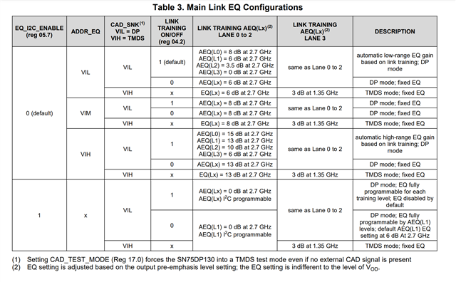
    Reference to Table 3 in the datasheet

    With EQ_I2C_ENABLE bit set to 1, they have two options of programmable EQ.

    Thanks

    David

  • Hello David,

    Please response from my customer below:

    My question was more about how to identify that an EQ sets of parameters are optimum for my hardware. How to find the best setup.
    I could get an example from my IP vendor using also a DP130 on his card, and they give me the function that writes into DP130 I2C registers the values. Please find below the routine, and let me know your comments:

    // Init the SN75DP130 on the Bitec Sink main link input
    // (on the Bitec daughter board)
    // Set the SN75DP130 equaliser as required by your design
    {
    unsigned char data[32];

    bitec_i2c_init(OC_I2C_MASTER_0_BASE);

    bitec_i2c_write(0x58, 0x01, 0x03);
    bitec_i2c_write(0x58, 0x03, 0x18); //disable squelch
    bitec_i2c_write(0x58, 0x05, 0xD2); //force EQ for lane 0, pre-emph 0_1, EQ_I2C_ENABLE
    bitec_i2c_write(0x58, 0x06, 0x10); //force EQ for lane 0, pre-emph 2_3
    bitec_i2c_write(0x58, 0x07, 0x52); //force EQ for lane 1, pre-emph 0_1
    bitec_i2c_write(0x58, 0x08, 0x10); //for

    Regards,

    Renan

  • Renan

    Do they have a scope that measure the raw waveform or the eye diagram at the DP130 output? They can tune the DP130 EQ base on the signal quality of the raw waveform or the eye diagram.

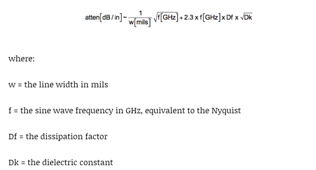
    If not, then they can estimate the PCB trace loss between the DP source and DP130 using the formula below,

    So with 5.4Gbps data rate (2.7GHz Nyquist frequency), 5mil trace width, Df of 0.02, and Dk of 4.3),

    =SQRT(2.7)/5+2.3*2.7*0.02*SQRT(4.3) = 0.586dB/in 

    Assume 6in trace, then the estimate PCB trace loss is 3.52dB.

    With estimate PCB trace loss of 3.52dB, you can set the DP130 EQ to roughly match up this value.

    Thanks

    David