Hello TI experts,
My customer is looking for the driver of SN65DSI84, linux kernel is 5.4 version.
Could you check the driver and source code for this version?
Best regards,
Chase
This thread has been locked.
If you have a related question, please click the "Ask a related question" button in the top right corner. The newly created question will be automatically linked to this question.
Hello TI experts,
My customer is looking for the driver of SN65DSI84, linux kernel is 5.4 version.
Could you check the driver and source code for this version?
Best regards,
Chase
Chase,
Here is a thread with the same question and a good response to your question. Please refer to https://e2e.ti.com/support/interface-group/interface/f/interface-forum/1124389/sn65dsi84-sn65dsi84-driver-request.
Thank you,
Zach
Dear Zach,
Thank you for your support. I will discuss it with my customer about the link which you noted.
and here is another question,
my customer tried to test SN65DSI84 on their own PCB, but they could not see nothing. (I2C communication is activated successfully but nothing happened after that.)
so could you give me some example codes to see just one color bar on LCD through the output?
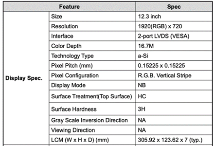
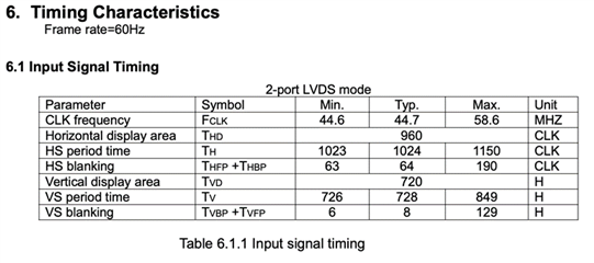
here is the specification of LCD which my customer used.


also I want you to review the schematic of my customer. I will send you asap. Thanks,
Best regards,
Chase
Hi Chase,
For blank screen issues, there is an FAQ you can refer the customer to here: https://e2e.ti.com/support/interface-group/interface/f/interface-forum/852871/faq-sn65dsi84-no-display-output-with-sn65dsi83-sn65dsi84-sn65dsi85. Make sure to use the DSI Tuner to configure the device and make sure the initialization sequence is being followed.
The SN65DSI84’s output clock frequency range is 25 – 154 MHz. Since the display panel’s frequency requirement is within range of the SN65DSI84’s supported clock frequencies, this display panel can be supported.
You will need to make sure that your DSI CLK will be supported with your intended bpp and # DSI data lanes. For further details, refer to https://e2e.ti.com/support/interface-group/interface/f/interface-forum/945185/faq-sn65dsi84-sn65dsi83-sn65dsi84-and-sn65dsi85-resolution-guide.
Thanks,
Zach
Dear Zach,
Thank you for your support. I will discus it with my customer.
and Is there any example codes for color bar on the LCD?
also I attach the schematic, please review it. Thanks.
Video_Switching_Board_SN65DSI84.pdf
Best regards,
Chase
Chase,
A few things on the schematic:
For the EN pin, the values of the RC circuitry need to make sure the low to high transition occurs after the Vcc supply has reached the minimum recommended operating voltage. For this reason, it is recommended to USE ACTIVE CIRCUITRY for better control of the RESET/EN timing.
Do you have 4.7k pull-up resistors to 1.8V power plane on I2C SCL and SDA?
For the ADDR pin, install PU or PD depending on the I2C Target addr configuration. DO NOT INSTALL BOTH.
For further information, see https://www.ti.com/lit/an/slla340a/slla340a.pdf?ts=1663251492285&ref_url=https%253A%252F%252Fwww.ti.com%252Fproduct%252FSN65DSI84.
When you refer to color bar I am assuming you are talking about enabling the pattern generation feature. The pattern generation feature can be enabled by setting the CHA_TEST_PATTERN bit at address 0x3C.
Thanks,
Zach
Hi,
Did you have any other questions?
If not, please click on the "this resolved my issue" button to close this thread.
Thank you,
Zach