This thread has been locked.

If you have a related question, please click the "Ask a related question" button in the top right corner. The newly created question will be automatically linked to this question.

TCAN1043-Q1: WAKE Pin Current Handling Capacity

Part Number: TCAN1043-Q1
Other Parts Discussed in Thread: TCAN1043

Hi,

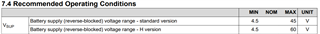
I went through TCAN1043 datasheet and as per that maximum voltage on Wake pin will be Vsup+0.3V.  In design, we are considering CAN driver wakeup from digital input and voltage on digital input will be up to 60V when switch is on.  So considering this requirement we are using voltage divider and CAN driver will detect high when battery voltage is between 30V to 60V(VSUP Voltage is 12V).  But with this we are exceeding maximum voltage rating on wake up pin. For more details go though snapshots. 

So let me know maximum current handling of WAKE pin with considering device reliability. 

Schematic:

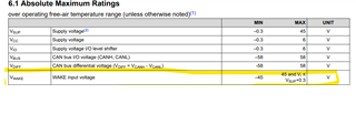
WAKE pin max rating:

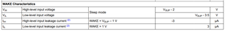
WAKE pin High and Low level detection

  • Hi Arvind,

    Exceeding the abs max voltage on the wake pin can do damage to the device even if you limit the current. The H version of this device can support a fault up to 70V on the WAKE pin but it is not expected that this pin has a voltage higher than the recommended VSUP voltage on it consistently and if that is the case then the lifetime of the device could be degraded.

    That being said the current that we spec in the datasheet is the output current on the wake pin due to a ground shift. The reason we don't spec an input current is because input pins don't see a large amount of current. As you can imagine the voltage potential on one side of the pin and on the other side of the pin is going to be the same and therefore there will be very little current. Obviously there is some voltage drop because the input pin doesn't have infinite resistance but it will be extremely small. Now you could see a voltage drop for a short period of time when the the voltage source is first turned on or there is a quick change in the voltage. This is due to the inherent capacitance of the pin and when that voltage is first applied there will be some sort of voltage drop that will quickly dissipate and reach steady state.

    That is all to say that the major requirement of this pin is that you do not exceed VSUP +0.3V and in normal operation if you get the H version of the device VSUP can be up to 60V max:

    I would think about supply the VSUP pin with the 30V-60V voltage or making sure that you voltage divide down the voltage to below the VSUP level. Currently with a 12V VSUP and 60V on your voltage divider scheme you would be violating ABS max.

    Best,

    Chris

  • Dear Chris,

    Thanks for replay,

    We are considering 12V for VSUP due to design requirement and We are considering WAKE pin max voltage will be  VSUP +0.3V due to ESD or internal MOSFET parasitic body diode. If so it will have some current limit. So let us know how we use this IC with considering with VSUP is at 12V and digital input will be from 30V to 60V.

    Also if we consider H  version, WAKE pin High level detection is at VSUP-2V and LOW is at 3.5V.  But in any system with WAKE up from external digital switch (From Wiring Harness) then there is high possibility that input will go above VSup+0.3 due to drop in wiring harness.
    SO let me know TI recommendation for condition in which Wake up pin vtg is more than Vsup.

  • Arvind,

    The current limit on the pin is 3 mA. However, like I said you just have to make sure that you are dividing down the voltage to below VSUP. With this current resistor scheme you are dividing down the voltage by about ~0.5. In reality probably a little bit more than half. If your voltage is at 60V then this would put you well above VSUP and would certainly damage the device.

    What does vtg mean in this sense?

    This pin is going to have very little current flowing through it since it is an input so I can't imagine overshoot being a large issue. But if you see that it is one during testing you could look at adding a Schottky diode to limit the maximum voltage on the pin or adding some more series resistance to limit the current further.

    Best,

    Chris